
GIGABYTE B650E AORUS STEALTH ICE
Contents
GIGABYTE B650E AORUS Stealth ICE Motherboard User Manual
Model: B650E AORUS STEALTH ICE
Brand: GIGABYTE
Introduction
This manual provides comprehensive instructions for the installation, operation, and maintenance of your GIGABYTE B650E AORUS Stealth ICE Motherboard. Please read this manual thoroughly before proceeding with installation to ensure proper setup and optimal performance.
The GIGABYTE B650E AORUS Stealth ICE Motherboard is designed to elevate your computing experience, featuring innovative designs and advanced features for exceptional performance and reliability. It supports AMD Ryzen 9000/8000/7000 Series Processors and DDR5 memory.
Package Contents
Before installation, verify that all items listed below are present in your motherboard package:
- GIGABYTE B650E AORUS Stealth ICE Motherboard
- User Manual (this document)
- Driver CD/USB (if included)
- SATA Cables
- Wi-Fi Antenna
- M.2 Screws/Standoffs
- Other accessories (check specific model for full list)

Image: The GIGABYTE B650E AORUS Stealth ICE Motherboard alongside its retail packaging, illustrating the product's appearance and branding.
Setup and Installation
This section guides you through the physical installation of the motherboard and its components.
1. Safety Precautions
- Always disconnect the power supply from the wall outlet before installing or removing any components.
- Wear an anti-static wrist strap to prevent electrostatic discharge (ESD) damage to components.
- Handle components by their edges, avoiding contact with pins or circuitry.
2. Motherboard Layout Overview

Image: A top-down view of the GIGABYTE B650E AORUS Stealth ICE Motherboard, highlighting the CPU socket, DIMM slots, and M.2 thermal heatsink.
Familiarize yourself with the various connectors and slots on the motherboard. Key areas include the CPU socket (AM5), DDR5 DIMM slots, PCIe slots, and M.2 slots.
3. CPU Installation
- Locate the AM5 CPU socket on the motherboard.
- Gently lift the load lever and open the load plate.
- Align the triangular mark on the CPU with the mark on the socket.
- Carefully place the CPU into the socket without forcing it.
- Close the load plate and push down the load lever until it clicks into place.

Image: An angled view of the GIGABYTE B650E AORUS Stealth ICE Motherboard, focusing on the AM5 CPU socket area and surrounding VRM heatsinks.
4. Memory (RAM) Installation
- Open the clips at both ends of the DDR5 DIMM slots.
- Align the notch on the memory module with the notch in the DIMM slot.
- Insert the memory module firmly into the slot until the clips snap into place.
- Install memory modules in pairs for dual-channel operation, referring to the motherboard's specific slot recommendations.
5. M.2 SSD Installation
The motherboard features M.2 EZ-Match for magnetic alignment and EZ-Latch Click/Plus for screwless installation of M.2 heatsinks and SSDs.
- Locate the M.2 slots and their corresponding heatsinks.
- For EZ-Latch Click heatsinks, simply unlatch and lift the heatsink.
- Insert the M.2 SSD into the slot at an angle.
- Gently push down the M.2 SSD and secure it using the EZ-Latch Plus mechanism (if available) or a screw.
- Reattach the M.2 heatsink, ensuring it clicks into place.
6. Graphics Card (PCIe) Installation
The PCIe UD Slot X provides 10X strength for graphics cards.
- Locate the PCIe 5.0 x16 slot.
- Open the retention clip at the end of the slot.
- Align the graphics card with the slot and press it down firmly until it seats correctly and the retention clip snaps into place.
- Secure the graphics card to the chassis with screws.
7. Connecting Peripherals and Power
- Connect the 24-pin ATX power connector and the 8-pin CPU power connector from your power supply to the motherboard.
- Connect SATA devices (SSDs/HDDs) to the SATA ports.
- Connect front panel headers (USB, audio, power, reset, LED indicators) according to the motherboard manual's pinout diagram.
- Install the Wi-Fi antenna using the WIFI EZ-Plug design for quick and easy installation.
- Connect USB devices, display cables (HDMI, DisplayPort), and audio devices to the rear I/O panel.
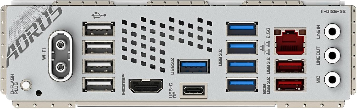
Image: A detailed view of the rear I/O panel of the GIGABYTE B650E AORUS Stealth ICE Motherboard, showing various USB ports, LAN, Wi-Fi antenna connectors, and audio jacks.
Operating Instructions
Once all components are installed and connected, you can proceed with initial boot-up and operating system installation.
1. Initial Boot-Up and BIOS Setup
- Connect your monitor, keyboard, and mouse.
- Power on your system.
- Press the DEL key repeatedly during startup to enter the UC BIOS.
- In the BIOS, verify that all installed components (CPU, RAM, SSDs) are detected.
- Set the boot order to your preferred installation media (USB drive or DVD).
- Save changes and exit BIOS.
The UC BIOS offers a user-centered intuitive UX with Quick Access functions for easy navigation and configuration.
2. Operating System Installation
Follow the on-screen prompts to install your chosen operating system (e.g., Windows, Linux). Ensure you have the necessary drivers ready, which can typically be downloaded from the GIGABYTE website or found on the included driver media.
3. Driver Installation
After OS installation, install the latest drivers for your motherboard components, including chipset, LAN, audio, and Wi-Fi. This ensures optimal performance and stability.
4. Sensor Panel Link
The motherboard includes an onboard video port for hassle-free in-chassis panel setup, allowing for custom system monitoring displays.
Maintenance
Proper maintenance can extend the lifespan and ensure the stable operation of your motherboard.
- Dust Removal: Regularly clean dust from inside your PC case, especially from heatsinks and fans, using compressed air. Ensure the system is powered off and unplugged before cleaning.
- BIOS Updates: Periodically check the GIGABYTE website for BIOS updates. BIOS updates can improve compatibility, stability, and performance. Follow the update instructions carefully.
- Driver Updates: Keep your drivers updated to the latest versions. This can resolve issues and improve system performance.
- Cable Management: Ensure cables inside the case are neatly managed to improve airflow and prevent obstruction.
Troubleshooting
This section provides solutions to common issues you might encounter.
| Problem | Possible Cause | Solution |
|---|---|---|
| System does not power on. | Loose power connections, faulty power supply, incorrect front panel wiring. | Check all power cables (24-pin ATX, 8-pin CPU) are securely connected. Verify front panel power button wiring. Test with a known good power supply if possible. |
| No display on monitor. | Graphics card not seated properly, monitor cable loose, faulty RAM. | Ensure graphics card is fully seated in PCIe slot. Check monitor cable connection. Reseat RAM modules. Try booting with one RAM stick at a time. |
| System reboots unexpectedly or crashes. | Overheating, unstable overclock, faulty RAM, driver issues. | Monitor CPU/GPU temperatures. Reset BIOS to default settings. Run memory diagnostic tools. Update chipset and other critical drivers. |
| M.2 SSD not detected. | Improper installation, BIOS settings, M.2 slot sharing with SATA ports. | Ensure M.2 SSD is fully seated. Check BIOS settings for M.2 slot enablement. Refer to motherboard manual for potential M.2/SATA port sharing limitations. |
| Wi-Fi or LAN not working. | Missing or incorrect drivers, antenna not connected, cable issue. | Install the latest Wi-Fi and LAN drivers from GIGABYTE's website. Ensure Wi-Fi antenna is securely connected. Check LAN cable. |
Specifications
| Feature | Detail |
|---|---|
| CPU Socket | AMD Socket AM5 (Supports AMD Ryzen 9000/8000/7000 Series Processors) |
| VRM Solution | Digital twin 12+2+2 phases |
| RAM Type | Dual Channel DDR5 (4 DIMMs with AMD EXPO Memory Module Support) |
| Memory Speed (OC) | Up to 8000MHz |
| PCIe Slot | PCIe UD Slot X (PCIe 5.0 x16 with 10X strength) |
| M.2 Slots | 1x PCIe 5.0 M.2 + 3x PCIe 4.0 M.2 (with EZ-Latch Click/Plus) |
| Networking | Wi-Fi 7, 2.5GbE LAN |
| USB Ports | USB 3.2 Gen 2x2 and others |
| BIOS | UC BIOS (User-Centred intuitive UX with Quick Access function) |
| Special Features | WIFI EZ-Plug, M.2 EZ-Match, Sensor Panel Link |
| Dimensions (LxWxH) | 9.61 x 12.01 x 1.38 inches |
| Item Weight | 6.4 pounds |
Warranty and Support
For detailed warranty information, please refer to the warranty card included with your product or visit the official GIGABYTE website. Warranty terms and conditions may vary by region.
For technical support, driver downloads, BIOS updates, and further product information, please visit the official GIGABYTE support website. You can also find FAQs and troubleshooting guides there.
Official GIGABYTE Website: www.gigabyte.com
Ask a question about this manual
Ask about setup, troubleshooting, compatibility, parts, safety, or missing instructions. Manuals+ will review the question and use this page’s manual context to help answer it.