1. Introduction
The eletechsup R4IOJ32 is a 32-channel RS485 multi-function IO core board designed for Modbus RTU input/output control. This compact board is suitable for integration into various PLC and HMI remote IO expansion systems. It supports flexible configuration of IO modes, including 24 Digital Inputs (DI) and 8 Digital Outputs (DO) for this specific variant, and allows for switching between NPN and PNP input/output levels.
This manual provides detailed instructions for the setup, operation, and maintenance of the R4IOJ32 24DI-8DO Only Board.
2. Features
- Flexible Power Supply: Supports DC 6-26V (with anti-reverse protection) or DC 4-5.5V (reverse connection prohibited). Only one power supply should be used at a time.
- Low Working Current: Operates at 9mA.
- Modbus RTU Support: Implements function codes for Write (05/06/15/16) and Read (01/02/03).
- Configurable IO Modes: Five function IO modes can be selected via jumpers: 32DI, 32DO, 16DI-16DO, 8DI-24DO, and 24DI-8DO.
- Adjustable IO Levels: Input and output levels (NPN/PNP) can be switched by modifying registers 0X00F5/0X00F6.
- Communication Anomaly Handling: Configurable restart (0X00F3) and output port closure (0X00F4) upon communication abnormalities.
- Input Mode: Supports 3.3V/5V TTL level input, with options for low-level (default) and high-level input.
- Output Mode: Provides 5V TTL level output, with options for low-level (default) and high-level output.
- Parallel Device Support: Up to 247 devices can be supported in parallel in Modbus command mode.
- Input Port Status: Supports both query (default) and automatic reporting.
- Configurable Baud Rates: 1200, 2400, 4800, 9600 (default), 19200, 38400, 57600, 115200, with None/Odd/Even Parity options.
- Compact Design: 2.54mm pin header interface for easy integration with Dupont wires or breadboards.
3. Specifications
| Parameter | Value |
|---|---|
| Model | R4IOJ32 (24DI-8DO Only Board) |
| Power Supply 1 | DC 6-26V (with anti-reverse protection) |
| Power Supply 2 | DC 4-5.5V (reverse connection prohibited) |
| Working Current | 9mA |
| Communication Interface | RS485 |
| Protocol | Modbus RTU |
| IO Modes | 32DI, 32DO, 16DI-16DO, 8DI-24DO, 24DI-8DO (selectable) |
| Input Level Support | 3.3V/5V TTL (low-level default, high-level selectable) |
| Output Level | 5V TTL (low-level default, high-level selectable) |
| Baud Rates | 1200, 2400, 4800, 9600 (default), 19200, 38400, 57600, 115200 |
| Parity | None, Odd, Even |
| Interface | 2.54mm Pin Header |
| Dimensions | 51mm x 34mm x 4mm |
| Weight | 8 grams |
The R4IOJ32 board is available in "Only Board" and "With Pin" versions. The current product is the "Only Board" version.

Figure 1: R4IOJ32 "Only Board" (left) and "With Pin" (right) versions.

Figure 2: R4IOJ32 PCB dimensions, showing 51.000mm length, 33.500mm width, and 2.540mm pin spacing.
4. Setup
4.1 Pinout Diagram
The R4IOJ32 board features a 2.54mm pin header interface for all connections. Refer to the pinout diagram below for proper wiring.
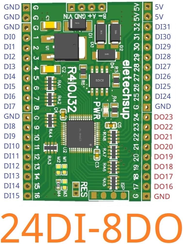
Figure 3: R4IOJ32 24DI-8DO Pinout Diagram. This diagram illustrates the layout of ground (GND), digital input (DI), digital output (DO), 5V power, VIN, and RS485 communication pins (A+, B-).
4.2 Power Supply Connection
The R4IOJ32 board offers two power supply options. Only one power supply should be connected at any given time.
- Power Supply 1 (VIN): DC 6-26V. This input includes anti-reverse connection protection.
- Power Supply 2 (5V): DC 4-5.5V. Reverse connection is prohibited for this input.

Figure 4: Power supply and RS485 port locations on the R4IOJ32 board. Note the two distinct power input options and the RS485 communication terminals.
4.3 IO Mode Selection
The R4IOJ32 is a multi-function board where the IO configuration can be changed using jumpers M1, M2, M3, and M4. These jumpers utilize 0603 0Ω resistors or wire links. The default configuration for this specific board is 24DI-8DO.
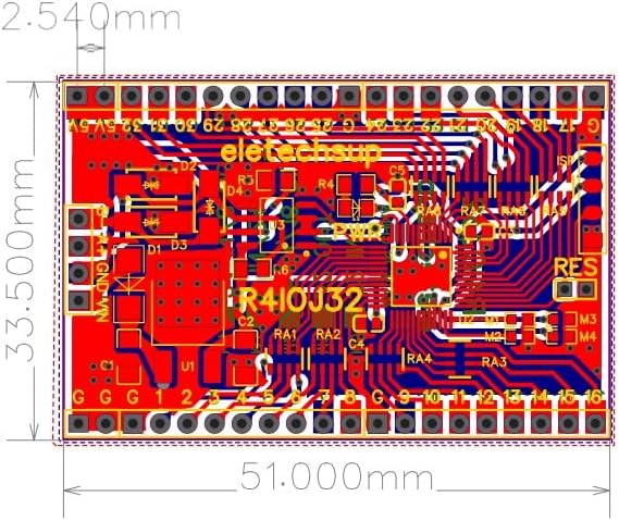
Figure 5: Location of M1-M4 jumpers for IO mode selection.
Refer to the table below for different IO mode configurations:

Figure 6: Jumper soldering configurations for various IO modes.
The back of the board also indicates the jumper positions for different modes:
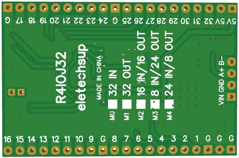
Figure 7: Back of the R4IOJ32 board indicating IO mode jumper settings.
4.4 Input and Output Level Switching (NPN/PNP)
The input and output levels can be configured as NPN or PNP types by modifying specific Modbus registers:
- NPN Input & NPN Output (Default): Set register 0X00F5 = 0, 0X00F6 = 0.
- PNP Input & PNP Output: Set register 0X00F5 = 1, 0X00F6 = 1.
- NPN Input & PNP Output: Set register 0X00F5 = 0, 0X00F6 = 1.
- PNP Input & NPN Output: Set register 0X00F5 = 1, 0X00F6 = 0.
The input mode supports 3.3V/5V TTL level, with low-level input as default and high-level input selectable. The output mode provides 5V TTL level, with low-level output as default and high-level output selectable.

Figure 8: Various IO configurations and NPN/PNP level settings. This image displays detailed pin assignments for different IO modes and level types.
5. Operating Instructions
5.1 Modbus RTU Communication
The R4IOJ32 communicates using the Modbus RTU protocol over RS485. It supports the following function codes:
- Write Functions: 05 (Write Single Coil), 06 (Write Single Register), 15 (Write Multiple Coils), 16 (Write Multiple Registers).
- Read Functions: 01 (Read Coils), 02 (Read Discrete Inputs), 03 (Read Holding Registers).
The input port status can be queried (default) or configured for automatic reporting.
5.2 Baud Rate and Parity Settings
The communication baud rate can be configured to one of the following values:
- 1200 bps
- 2400 bps
- 4800 bps
- 9600 bps (Default)
- 19200 bps
- 38400 bps
- 57600 bps
- 115200 bps
Parity options include None, Odd, or Even.
5.3 Handling Communication Abnormalities
The board can be configured to respond to communication abnormalities:
- Restart on Anomaly: By setting register 0X00F3, the board can be configured to restart if communication becomes abnormal.
- Close Outputs on Anomaly: By setting register 0X00F4, all output ports can be configured to close if communication becomes abnormal.
6. Maintenance
6.1 Factory Reset
To restore the board to its factory settings, short the RES jumper for 5 seconds. Refer to Figure 4 for the location of the RES jumper.
6.2 General Care
Keep the board clean and free from dust and moisture. Avoid exposing it to extreme temperatures or static discharge. Handle with care to prevent damage to the delicate components and pin headers.
7. Troubleshooting
If you encounter issues with the R4IOJ32 board, consider the following:
- No Power: Verify that only one power supply is connected and that it provides the correct voltage (DC 6-26V or DC 4-5.5V) with correct polarity.
- Communication Errors: Check RS485 wiring (A+ to A+, B- to B-), baud rate, and parity settings. Ensure the Modbus address is correctly configured and unique if multiple devices are on the bus.
- Incorrect IO Behavior: Confirm that the correct IO mode is selected via the M1-M4 jumpers (refer to Section 4.3). Verify NPN/PNP level settings in registers 0X00F5/0X00F6 (refer to Section 4.4).
- Outputs Not Responding: Check if the communication anomaly setting (register 0X00F4) is configured to close outputs. Ensure the input signals are within the supported 3.3V/5V TTL levels.
- Board Unresponsive: Attempt a factory reset by shorting the RES jumper for 5 seconds (refer to Section 6.1).
8. Support
For more detailed documentation, technical assistance, or specific inquiries not covered in this manual, please contact eletechsup customer support directly. Refer to the product packaging or the seller's website for contact information.


