1. Introduction
This manual provides essential information for the safe and efficient operation, installation, and maintenance of your WENBIXIA CW100 Inverter Frequency Converter. The CW100 series is a Variable Frequency Drive (VFD) designed to control the speed of AC motors, offering features such as fast start/stop response and high torque at low speeds. Please read this manual thoroughly before installation and operation to ensure proper usage and to prevent damage or injury.
2. Safety Information
WARNING: Electrical Hazard. Improper installation or operation can lead to serious injury or death. Only qualified personnel should install, operate, and maintain this equipment.
- Always disconnect power before performing any wiring, inspection, or maintenance. Wait at least 5 minutes after disconnecting power for capacitors to discharge. The "DANGER 5 min" label on the unit indicates this critical safety period.
- Ensure proper grounding of the VFD and the motor.
- Do not touch electrical components when power is applied.
- Verify input voltage and phase match the VFD's specifications before connecting power.
- Install the VFD in a clean, dry, and well-ventilated environment, away from direct sunlight, corrosive gases, and excessive vibration.
- Use appropriate personal protective equipment (PPE) when working with electrical equipment.

Image: Close-up of the WENBIXIA CW100 VFD control panel and main terminal blocks, clearly showing the "DANGER 5 min" warning label, indicating the required waiting period after power disconnection before handling.
3. Product Overview
The WENBIXIA CW100 Inverter Frequency Converter is designed for precise motor speed control in various industrial applications. Its robust design ensures reliable performance and extended service life.
3.1 Key Features
- Easy to Use: Simple operation and wiring process.
- Variable Frequency Drive: Provides fast start/stop response and high torque at low speeds.
- Optimized Cooling: Casing designed with multiple ventilation holes, ensuring sufficient cooling space between components for longer service life.
- Low Noise & EMI: Engineered for reduced operational noise and electromagnetic interference.
3.2 Applicable Motors
The CW100 VFD is suitable for a wide range of motor applications, including but not limited to:
- Spindles
- Routers
- Milling machines
- Drilling machines
- Winding machines
- Mixers
- Extruders
- Slitters
- Winders
- Compressors
- Ventilators
- Pumps
- Grinders
- Conveyors
- Elevators
- Centrifuges

Image: Front view of the WENBIXIA CW100 VFD, showcasing the control panel, display, and main power input/output terminal blocks.
4. Specifications
The WENBIXIA CW100 series offers various power ratings and input/output configurations. The specific model covered by this manual is the 5.5KW, 3-Phase 380V input/output variant.
| Parameter | Value (5.5KW, 3PH380V-3PH380V Model) |
|---|---|
| Model Series | CW100 |
| Rated Power | 5.5 KW |
| Input Voltage | 3-Phase 380V |
| Output Voltage | 3-Phase 380V |
| Input/Output Phase | 3-Phase Input, 3-Phase Output |
| Item Weight | 7.1 ounces (Note: This weight seems unusually low for a 5.5KW VFD and may refer to packaging or a smaller variant. Please verify actual product weight upon receipt.) |
| Package Dimensions | 0.39 x 0.39 x 0.39 inches (Note: These dimensions seem unusually small for a 5.5KW VFD and may refer to packaging or a smaller variant. Please verify actual product dimensions upon receipt.) |
| Manufacturer | WENBIXIA |
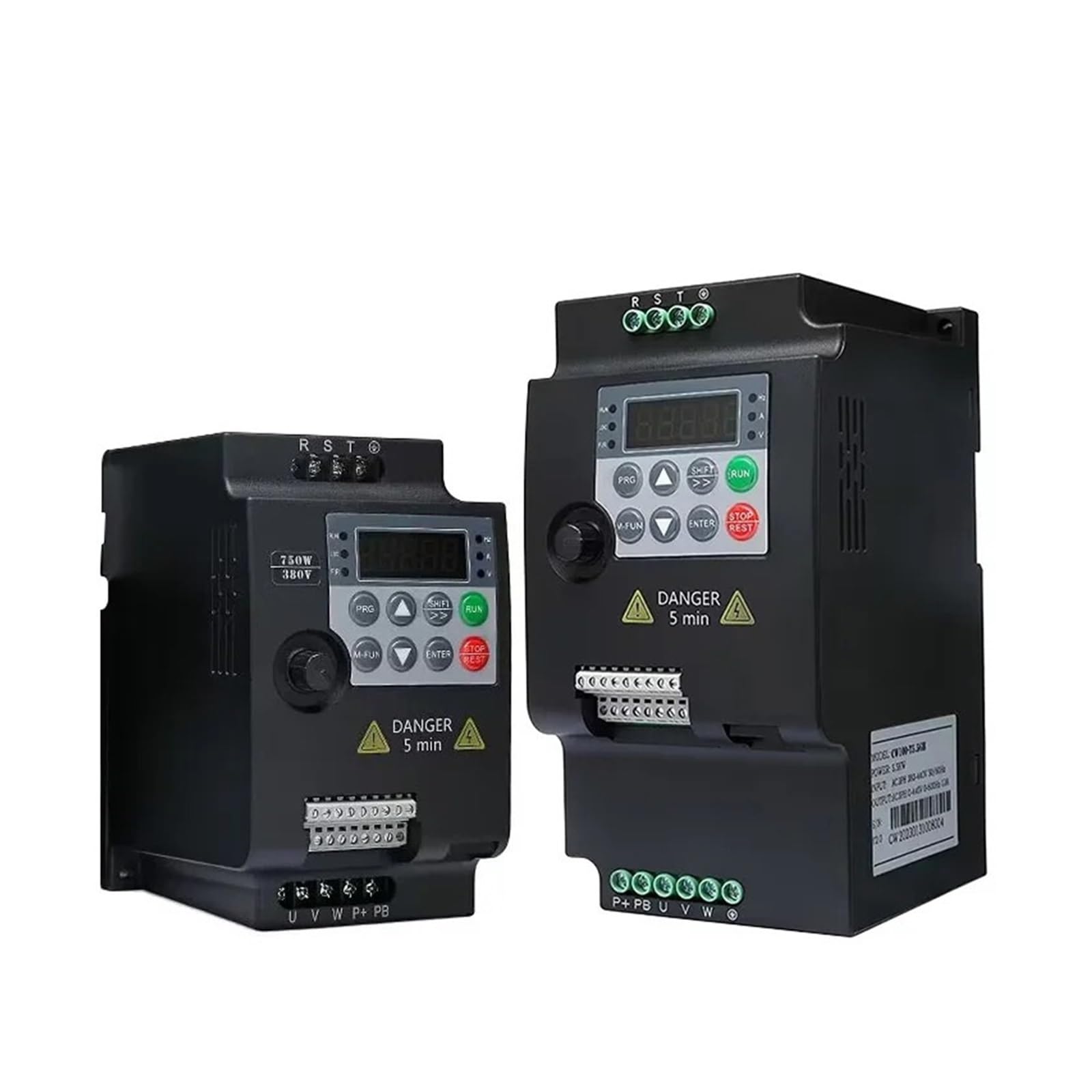
Image: WENBIXIA CW100 5.5KW VFD showing approximate physical dimensions: 180mm height, 95mm width, and 120mm depth. This image provides a visual reference for the unit's size.

Image: Side view of the WENBIXIA CW100 VFD, displaying the product label with model information, power rating (5.5KW), and input/output specifications.
5. Setup and Wiring
Proper installation and wiring are critical for the safe and correct operation of the VFD. Refer to the wiring diagrams provided with your unit for detailed connections.
5.1 Installation Environment
- Mount the VFD vertically on a stable, non-flammable surface.
- Ensure adequate clearance around the unit for proper ventilation and heat dissipation. The multi-hole casing design relies on airflow for cooling.
- Avoid locations with excessive dust, moisture, corrosive gases, or direct sunlight.
- Operating temperature range: 0°C to 40°C (32°F to 104°F).
5.2 Wiring Instructions
Before wiring, ensure all power sources are disconnected and locked out. Wait the specified discharge time (at least 5 minutes) before touching any terminals.
- Power Input (R, S, T): Connect the 3-phase 380V AC power supply to the R, S, T terminals. Ensure correct phase sequence.
- Motor Output (U, V, W): Connect the motor's three-phase windings to the U, V, W terminals.
- Grounding (PE): Connect the protective earth (ground) wire to the PE terminal on both the VFD and the motor. This is essential for safety.
- Braking Resistor (P+, PB): If an external braking resistor is required for applications with frequent deceleration or high inertia loads, connect it between the P+ and PB terminals.
- Control Terminals: The control terminal block provides connections for external control signals.
- Analog Inputs: 10V (power supply for potentiometer), A1 (analog input 1), GND (analog ground), AOI (analog output current), AOV (analog output voltage).
- Digital Inputs: D1, D2, D3, D4, D5 (programmable digital inputs), 24V (24V power supply for digital inputs).
- Relay Outputs: TA, TB, TC (relay contacts for status indication or control).
- Communication: A+, B- (RS485 communication interface).
- Ethernet Port: An RJ45 port may be present for network communication or programming.

Image: Detailed view of the WENBIXIA CW100 VFD's control terminal block, showing connections for analog inputs, digital inputs, relay outputs, and the RS485 communication interface (A+, B-). An RJ45 port is also visible.
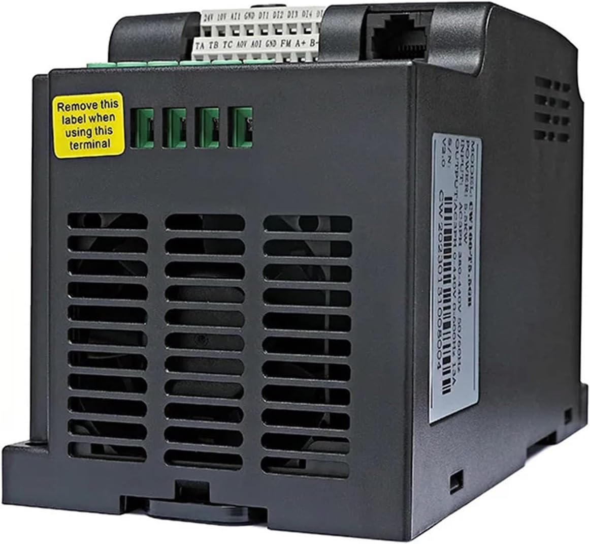
Image: Side view of the WENBIXIA CW100 VFD, highlighting the cooling vents designed for efficient heat dissipation and a yellow warning label indicating to remove it when using specific terminals.
6. Operating Instructions
The CW100 VFD features a user-friendly control panel for local operation and parameter setting.
6.1 Control Panel Overview
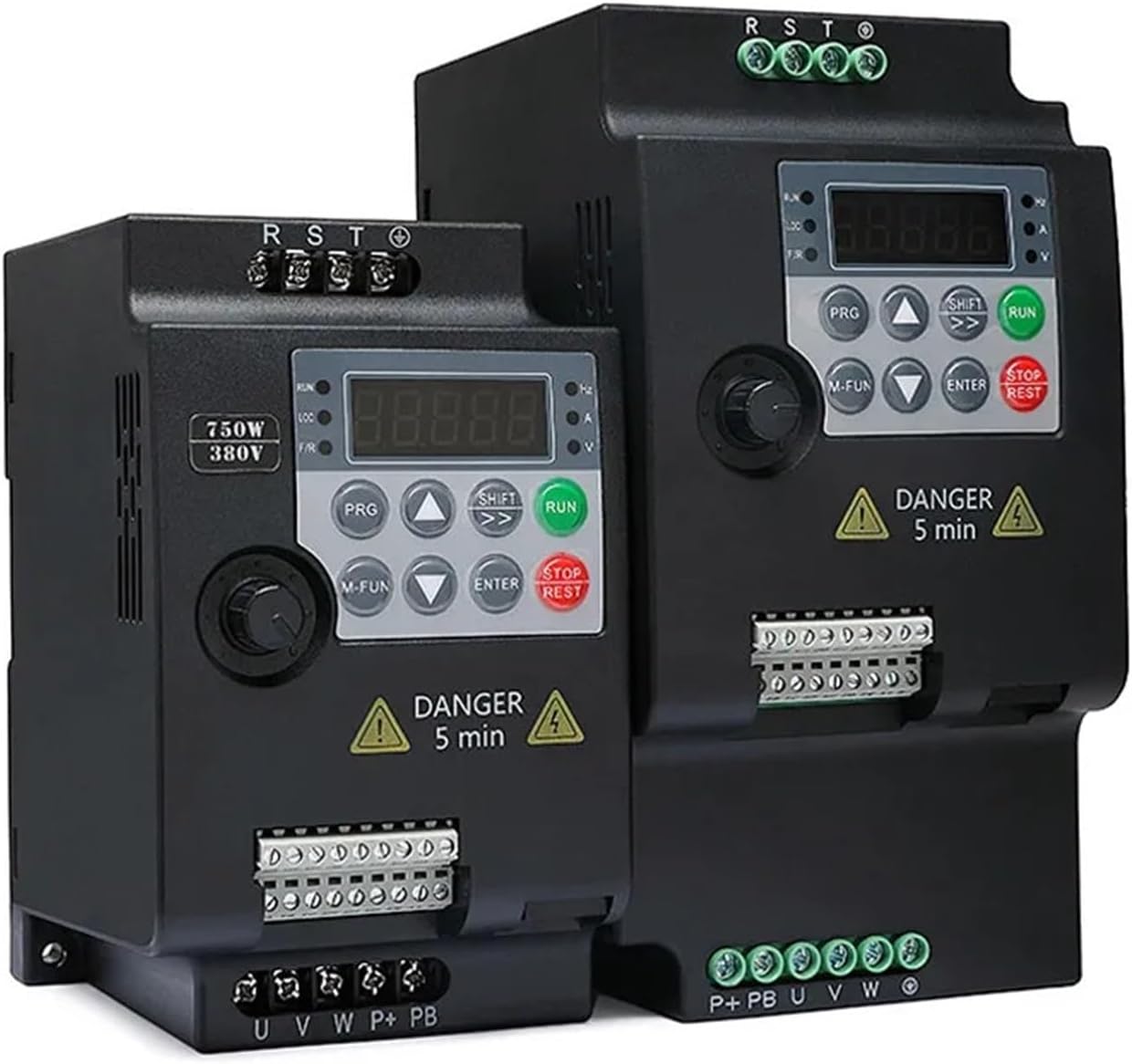
Image: Two WENBIXIA CW100 VFD units displayed side-by-side, illustrating the consistent control panel layout across different power ratings within the series.
- Display: A 4-digit LED display shows frequency, current, voltage, and other operational parameters. Indicators for Hz, A, V, FWD/REV, LOC/REM are also present.
- PRG (Program): Enters/exits parameter setting mode.
- M-FUN (Multi-Function): Accesses multi-function menus or special operations.
- SHIFT: Shifts cursor position during parameter editing or displays different parameters.
- RUN: Starts the motor.
- STOP/RESET: Stops the motor or clears fault indications.
- ENTER: Confirms parameter settings or enters sub-menus.
- Up/Down Arrows: Adjusts parameter values or navigates through menus.
- Rotary Knob: Used for fine adjustment of frequency or parameter values.
6.2 Basic Operation
- Power On: After verifying all connections are secure and correct, apply power to the VFD. The display will light up.
- Parameter Setting (if needed):
- Press PRG to enter parameter setting mode.
- Use Up/Down arrows to navigate through parameter groups and individual parameters.
- Press ENTER to select a parameter for editing.
- Use Up/Down arrows or the Rotary Knob to change the value. Use SHIFT to move between digits.
- Press ENTER to save the new value.
- Press PRG to exit parameter setting mode.
- Start Motor: Press the RUN button. The motor will accelerate to the set frequency.
- Adjust Frequency: Use the Up/Down arrows or the Rotary Knob to adjust the output frequency (motor speed) during operation.
- Stop Motor: Press the STOP/RESET button. The motor will decelerate and stop.
7. Maintenance
Regular maintenance helps ensure the longevity and reliable operation of your WENBIXIA CW100 VFD.
- Cleaning: Periodically clean the VFD's exterior and cooling vents to prevent dust accumulation, which can hinder heat dissipation. Use a soft, dry cloth or compressed air. Ensure power is disconnected before cleaning.
- Inspection: Regularly inspect wiring connections for tightness and signs of wear or damage. Check for any unusual noises or odors during operation.
- Environment: Ensure the operating environment remains within specified temperature and humidity ranges.
- Capacitor Life: Electrolytic capacitors have a finite lifespan. If the VFD is in continuous operation for many years, consider professional inspection or replacement of capacitors.
8. Troubleshooting
This section provides solutions to common issues you might encounter. For problems not listed here or if issues persist, contact technical support.
| Problem | Possible Cause | Solution |
|---|---|---|
| VFD does not power on | No input power; Blown fuse; Incorrect wiring. | Check power supply; Inspect fuses; Verify input wiring (R, S, T). |
| Motor does not run | VFD in stop mode; Fault tripped; Incorrect motor wiring; Parameter settings incorrect. | Press RUN; Check for fault codes and clear with STOP/RESET; Verify motor wiring (U, V, W); Review basic operating parameters. |
| Motor runs in wrong direction | Incorrect phase sequence for motor; Direction parameter set incorrectly. | Swap any two of the motor output wires (U, V, W); Check and adjust the direction parameter in the VFD settings. |
| Overcurrent (OC) fault | Motor overload; Short circuit in motor or wiring; Acceleration time too short. | Reduce motor load; Check motor and wiring for shorts; Increase acceleration time parameter. |
| Overvoltage (OV) fault | Input voltage too high; Deceleration time too short; Regenerative load. | Check input voltage; Increase deceleration time parameter; Consider adding a braking resistor. |
9. Warranty and Support
For warranty information, please refer to the documentation included with your purchase or contact your vendor. WENBIXIA provides technical support for its products. If you require assistance with installation, operation, or troubleshooting, please contact WENBIXIA customer service or your local distributor.
Please have your product model (CW100) and serial number ready when contacting support.


