1. Introduction
This manual provides essential information for the safe and efficient installation, operation, and maintenance of the MOLLIFII 6C053-A Alternating Relay. Please read this manual thoroughly before using the product and retain it for future reference.
The MOLLIFII 6C053-A is an alternating relay designed to manage two loads by switching power between them, ensuring even wear and extending the lifespan of connected equipment. It features an 8-pin octal base for plug-in mounting and operates with a 240V AC coil voltage.
2. Safety Information
WARNING: Risk of Electric Shock
- Always disconnect power before installing, servicing, or removing the relay.
- Installation and maintenance should only be performed by qualified personnel.
- Ensure all wiring conforms to local and national electrical codes.
- Do not operate the relay if it appears damaged.
- Verify correct voltage and current ratings before connecting to loads.
3. Product Overview
The MOLLIFII 6C053-A Alternating Relay is a robust electrical component designed for reliable load management. Key features include:
- Model: 6C053-A
- Coil Voltage: 240V AC
- Contact Form: DPDT (Double Pole Double Throw)
- Contact Rating (AC): 10 A @ 240V
- Contact Rating (DC): 10 A @ 28V
- Number of Pins: 8
- Base Type: Octal
- Mounting Style: Plug-In
- Operating Modes: Alternate, Always Energize Load 1, Always Energize Load 2
- Status Indicator: LED indicates which load is energized.
- Dimensions: Body Depth 2.9 in, Body Height 2.4 in, Body Width 1.7 in
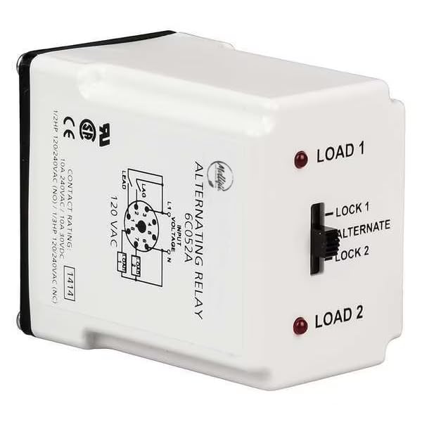
Figure 1: MOLLIFII 6C053-A Alternating Relay. This image displays the white casing of the relay, highlighting its key features. Visible details include the input voltage specifications (L1, N, 120 VAC), contact rating information (10A 240VAC/10A 30VDC, 1/2HP 120/240VAC NO, 1/3HP 120/240VAC NC), and control elements. These include two red LED indicators labeled "LOAD 1" and "LOAD 2", and a three-position selector switch with settings for "LOCK 1", "ALTERNATE", and "LOCK 2". The relay also prominently features CE and UL certifications. A wiring diagram for the 8-pin octal base is also visible, showing connections for LEAD, LAG, L1, N, and two loads.
4. Setup and Installation
- Power Disconnection: Ensure all power to the circuit is disconnected at the main breaker before beginning installation.
- Mounting: The 6C053-A relay is designed for plug-in mounting into a compatible 8-pin octal base (not included). Secure the base in the desired location.
- Wiring: Refer to the wiring diagram on the relay unit (and Figure 1) for correct connections.
- Connect the 240V AC coil voltage to the appropriate terminals (L1 and N as indicated).
- Connect Load 1 and Load 2 according to your application requirements.
- Ensure all connections are secure and properly insulated.
- Relay Insertion: Carefully insert the 8-pin relay into its octal base, ensuring all pins align correctly.
- Power Restoration: Once installation is complete and verified, restore power to the circuit.
5. Operating Instructions
The MOLLIFII 6C053-A Alternating Relay offers three operating modes, selectable via the switch on the front panel:
- ALTERNATE Mode: In this mode, the relay will alternate power between Load 1 and Load 2 with each subsequent activation of the control input. For example, if Load 1 is energized on the first cycle, Load 2 will be energized on the next, and so on. This mode is ideal for applications requiring even usage of two loads.
- LOCK 1 Mode: When the switch is set to LOCK 1, the relay will consistently energize Load 1 whenever the control input is active, regardless of previous cycles. Load 2 will remain de-energized.
- LOCK 2 Mode: When the switch is set to LOCK 2, the relay will consistently energize Load 2 whenever the control input is active, regardless of previous cycles. Load 1 will remain de-energized.
The red LED indicators labeled "LOAD 1" and "LOAD 2" will illuminate to show which load is currently energized by the relay.
6. Maintenance
The MOLLIFII 6C053-A Alternating Relay is designed for long-term, reliable operation with minimal maintenance. However, periodic checks are recommended:
- Visual Inspection: Periodically inspect the relay and its connections for any signs of damage, discoloration, or loose wiring.
- Cleaning: Ensure the relay and its base are kept clean and free from dust and debris. Use a dry, soft cloth for cleaning. Do not use liquid cleaners.
- Connection Integrity: Verify that all electrical connections remain tight and secure.
Always disconnect power before performing any maintenance.
7. Troubleshooting
If the MOLLIFII 6C053-A Alternating Relay is not functioning as expected, consider the following:
| Problem | Possible Cause | Solution |
|---|---|---|
| Relay does not energize any load. | No power to the coil; incorrect wiring; faulty relay. | Check power supply to the relay coil (240V AC). Verify all wiring connections. Test the relay with a known good power source if possible. |
| Only one load energizes, even in ALTERNATE mode. | Switch set to LOCK 1 or LOCK 2; issue with control input signal; faulty relay. | Ensure the selector switch is set to "ALTERNATE". Verify the control input signal is cycling correctly. |
| LED indicators are off or incorrect. | No power; faulty LED; relay not switching. | Check power. If relay is switching loads but LEDs are off, the LEDs may be faulty. If relay is not switching, refer to other troubleshooting steps. |
If troubleshooting steps do not resolve the issue, contact MOLLIFII customer support.
8. Specifications
| Parameter | Value |
|---|---|
| Model Number | 6C053-A |
| Coil Voltage | 240V AC |
| Contact Form | DPDT |
| Contact Rating (AC) | 10 A @ 240V |
| Contact Rating (DC) | 10 A @ 28V |
| Horsepower Rating (NO) | 1/2 HP @ 120/240V AC |
| Horsepower Rating (NC) | 1/3 HP @ 120/240V AC |
| Number of Pins | 8 |
| Base Type | Octal |
| Mounting Style | Plug-In |
| Operating Modes | Alternate, Always Energize Load 1, Always Energize Load 2 |
| Status Indicator | LED (Indicates first load to be energized) |
| Power Consumption | 3 VA |
| Body Depth | 2.9 in |
| Body Height | 2.4 in |
| Body Width | 1.7 in |
| Manufacturer | MOLLIFII |
| ASIN | B0DB6G9QCS |
9. Warranty and Support
For warranty information or technical support regarding your MOLLIFII 6C053-A Alternating Relay, please contact MOLLIFII customer service through their official channels. Please have your product model number (6C053-A) and purchase details available when contacting support.


