1. Introduction
This manual provides comprehensive instructions for the Anysecu AnyTone AT-6666pro 10 Meter Radio. It covers the features, setup, operation, and maintenance of your mobile transceiver. Please read this manual thoroughly before operating the device to ensure proper use and to maximize its performance.
Key Features:
- LCD display with 7 color options and backlight dimming.
- Supports FM, AM, USB, LSB, CW, and PA modes.
- High power output: 80W (PEP) for AM/SSB, 50W for FM.
- Frequency Tuning Steps: 10Hz, 100Hz, 1KHz, 5KHz, 10KHz, 100KHz, 1MHz.
- ± 500Hz, 5KHz Clarifier (R/T/R+T selectable).
- Flexible menu functions and PC programming software compatibility.
- RX and TX NRC Noise Reduction.
- SQ, ASQ Function (FM and AM mode).
- RF GAIN and RF PWR Adjustment.
- VFO / BAND / Memory Channel Modes.
- Repeater Shift / Offset Frequency Function.
- CTCSS/DCS with RX/TX Split functions.
- SCAN Function, NB/ANL Function, DW DUAL-WATCH Function.
- SWR, S/RF meter Function.
- TOT function, HI-CUT Function, EMG CALL.
- SWR Protection and Power Supply Voltage Protection.
- Key-Lock Function, DTMF Function, BEEP Prompt.
- Enhanced VOX Function (VOX.SPK supports digital mode operation).
2. What's in the Box
Upon unpacking, please verify that all the following items are included in your package. If any items are missing or damaged, contact your dealer immediately.
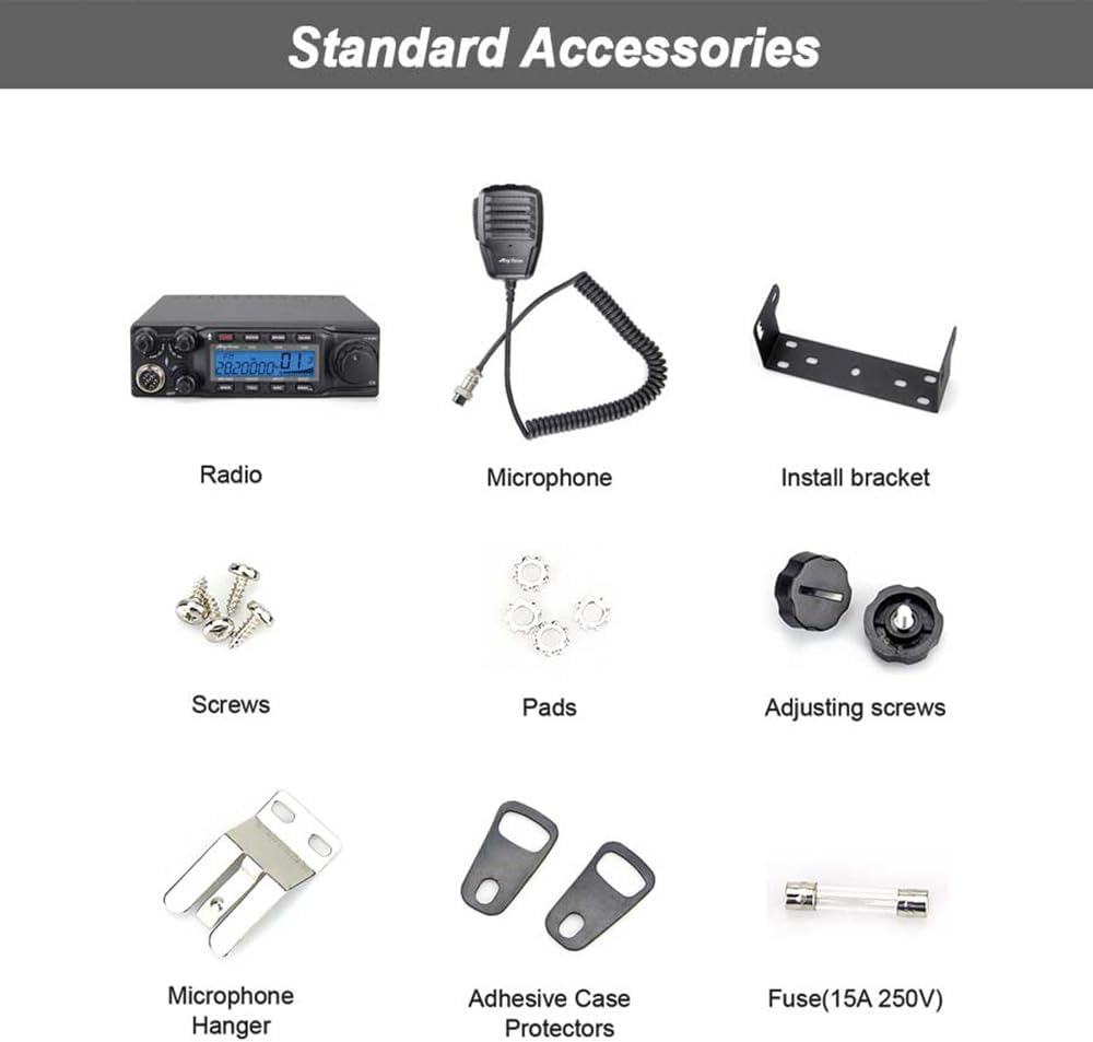
Image: Standard Accessories. This image displays all components included with the Anysecu AnyTone AT-6666pro radio. It shows the main radio unit, microphone, power cable, mounting bracket, various screws, pads, adjusting screws, a microphone hanger, adhesive case protectors, and a 15A 250V fuse.
- AnyTone AT-6666pro Radio Unit
- Microphone
- Power Cable
- Mounting Bracket
- Screws
- Pads
- Adjusting Screws
- Microphone Hanger
- Adhesive Case Protectors
- Fuse (15A 250V)
- User Manual (this document)
3. Setup and Installation
3.1 Mounting the Radio
The AT-6666pro can be mounted in a vehicle or at a fixed station using the provided mounting bracket.
- Choose a secure location that does not obstruct driving or air bag deployment in a vehicle.
- Use the mounting bracket as a template to mark drill holes.
- Drill pilot holes and secure the bracket using the supplied screws.
- Attach the radio to the bracket using the adjusting screws, ensuring it is firmly in place.
3.2 Connecting the Microphone
Connect the 6-pin connector of the microphone to the corresponding port on the front panel of the radio.

Image: Microphone Diagram. This diagram illustrates the AnyTone microphone, highlighting its key components: the Push-To-Talk (PTT) button, UP and DOWN buttons for channel/frequency adjustment, a user-defined PF button, the microphone element, and the 6-pin connector for attachment to the radio.
3.3 Power Connection
Connect the supplied power cable to the power input on the rear of the radio. Ensure the red wire connects to the positive (+) terminal of your 13.8V DC power source and the black wire to the negative (-) terminal. Install the fuse inline with the positive wire.
3.4 Antenna Connection
Connect a suitable 10-meter band antenna (not included) to the antenna connector on the rear of the radio. Ensure the antenna is properly tuned for the operating frequency to prevent damage to the transceiver.
4. Operating Instructions
This section details the various functions and controls of your AT-6666pro radio. Refer to the front panel diagram for control locations.

Image: AT-6666pro Front Panel Features. This image displays the front panel of the Anysecu AnyTone AT-6666pro radio, with a numbered list of 31 features. These numbers correspond to specific buttons, knobs, and display elements on the radio, illustrating their functions such as LCD display, mode selection, frequency tuning steps, clarifier, noise reduction, and various other operational controls.
4.1 Basic Operation
- Power On/Off: Rotate the VOL/OFF knob clockwise to turn on the radio. Rotate counter-clockwise until it clicks to turn off.
- Volume Adjustment: Rotate the VOL knob to adjust the audio output level.
- Squelch (SQ/ASQ): Adjust the SQ knob to eliminate background noise when no signal is present. The ASQ (Automatic Squelch) function can be activated for automatic noise control in FM and AM modes.
- Mode Selection: Press the MODE button to cycle through FM, AM, USB, LSB, CW, and PA modes.
- Frequency Tuning: Use the main VFO knob to adjust the operating frequency. The tuning step can be changed via menu settings.
4.2 Advanced Functions
- Clarifier: Use the CLARIFIER knob to fine-tune the receive or transmit frequency, especially useful in SSB modes. Select R (Receive), T (Transmit), or R+T (Both) via menu.
- RF GAIN: Adjusts the sensitivity of the receiver. Turn clockwise for higher sensitivity.
- RF PWR: Adjusts the transmit power output.
- NRC Noise Reduction: Activates the Noise Reduction Circuit for both RX and TX to improve audio clarity.
- SCAN Function: Initiates scanning of frequencies or memory channels.
- DW (DUAL-WATCH) Function: Monitors two frequencies simultaneously.
- CTCSS/DCS: Enables selective calling using Continuous Tone-Coded Squelch System or Digital Coded Squelch. Supports RX/TX split functions.
- VOX Function: Voice-Operated Transmit allows hands-free operation. Adjust sensitivity as needed.
- Key-Lock Function: Locks the keypad to prevent accidental changes.
- EMG CALL: Activates emergency call function.
5. Maintenance
5.1 General Care
- Keep the radio clean and free from dust. Use a soft, dry cloth for cleaning.
- Avoid exposing the radio to extreme temperatures, direct sunlight, or moisture.
- Do not use harsh chemicals or abrasive cleaners.
5.2 Fuse Replacement
If the radio does not power on, check the fuse in the power cable. Replace it with a fuse of the same rating (15A 250V) if blown. Always disconnect power before replacing the fuse.
6. Troubleshooting
This section addresses common issues you might encounter with your AT-6666pro radio.
- Radio does not power on:
- Check power cable connections.
- Verify power source voltage (13.8V DC).
- Inspect and replace the fuse if blown.
- Ensure the VOL/OFF knob is turned clockwise.
- No audio output:
- Increase the VOL knob.
- Adjust the SQ knob to ensure it's not set too high.
- Check speaker connection if using an external speaker.
- Poor transmit or receive performance:
- Check antenna connection and ensure it is properly tuned.
- Verify SWR (Standing Wave Ratio) using the built-in SWR meter. High SWR can indicate antenna issues.
- Adjust RF GAIN and RF PWR settings.
- Ensure correct operating mode (FM, AM, USB, LSB, CW).
- SWR Protection activated:
The radio has built-in SWR protection. If activated, it indicates a high SWR condition, which can damage the radio. Immediately check your antenna system for faults (e.g., short circuit, open circuit, improper tuning).
- Power Supply Voltage Protection activated:
This feature protects the radio from incorrect input voltage. Verify your power supply is providing a stable 13.8V DC.
7. Specifications
| Feature | Specification |
|---|---|
| Model Number | AT-6666pro |
| Brand | ANYSECU |
| Frequency Range | 28-29.7 MHz (10 Meter Band) |
| Modes | FM, AM, USB, LSB, CW, PA |
| Output Power (AM/SSB) | 80W (PEP) |
| Output Power (FM) | 50W |
| Number of Channels | 40 |
| Frequency Tuning Steps | 10Hz, 100Hz, 1KHz, 5KHz, 10KHz, 100KHz, 1MHz |
| Clarifier | ± 500Hz, 5KHz (R/T/R+T selectable) |
| Color | Black |
| Talking Range Maximum | 80 Kilometer (approx. 50 miles, dependent on conditions) |
| Water Resistance Level | Not Water Resistant |
| Item Weight (Product) | 1.3 kg (approx. 2.87 lbs) |
| Outer Box Weight | 2.5 kg (approx. 5.5 lbs) |
| Dimensions (Radio) | 158mm (W) x 48mm (H) x 250mm (D) (approx. 6.2 x 1.9 x 9.8 inches) |

Image: Product Dimensions. This image provides a multi-view diagram of the Anysecu AnyTone AT-6666pro radio, detailing its physical dimensions: 158mm width, 48mm height, and 250mm depth. It also specifies the product weight as 1.3kg and the outer box weight as 2.5kg.
8. Warranty and Support
8.1 Product Warranty
The Anysecu AnyTone AT-6666pro radio body is covered by a 1-year warranty from the date of purchase. This warranty covers manufacturing defects under normal use. Please retain your proof of purchase for warranty claims.
The warranty does not cover damage caused by misuse, accidents, unauthorized modifications, or improper installation.
8.2 Customer Support
For technical assistance, troubleshooting, or warranty service, please contact your authorized Anysecu dealer or visit the official Anysecu website for support resources.


