1. Introduction
The Proster Digital Multimeter (Model PST237-238) is a versatile and high-precision True RMS (TRMS) instrument designed for measuring various electrical parameters. It is suitable for a wide range of applications, from home use and hobbyist projects to professional electrical and industrial settings. This manual provides comprehensive instructions for the safe and effective use of your multimeter.
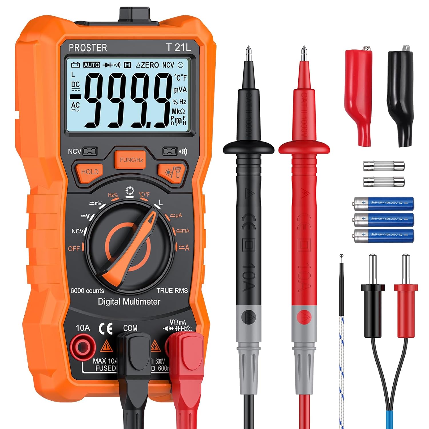
Figure 1: Proster Digital Multimeter and included accessories. The image displays the orange multimeter, black and red test leads, alligator clips, temperature probe, spare fuses, batteries, screwdriver, and user manual, all neatly arranged.
2. Safety Information
Always adhere to the following safety precautions to prevent personal injury or damage to the multimeter:
- Do not exceed the maximum input values specified for each measurement range.
- Ensure the test leads are properly connected and the function switch is set to the correct range before making any measurements.
- Exercise extreme caution when working with live circuits. High voltages can be dangerous.
- Inspect the test leads for any damage (e.g., cracked insulation) before use. Replace damaged leads immediately.
- Do not operate the multimeter if it appears damaged or if the battery cover is not securely closed.
- Remove test leads from the circuit before changing functions.
- The multimeter features built-in double safety tubes and overload protection. However, always operate within specified limits.

Figure 2: Internal components of the multimeter, highlighting the built-in double safety tube and overload protection circuit. This image shows the multimeter casing opened to reveal the green circuit board with various electronic components and fuses.
3. Product Components
Familiarize yourself with the main parts of your Proster Digital Multimeter:
- LCD Display: Large, backlit screen for clear readings.
- Function Knob: Rotary switch to select measurement modes.
- Function Buttons: Buttons for specific features like HOLD, Backlight/Flashlight, NCV, etc.
- Input Jacks: Ports for connecting test leads (COM, VΩmA, 10A).
- Test Leads: Red and black probes for making electrical connections.
- Temperature Probe: For temperature measurements.
- Kickstand: Integrated stand for convenient viewing angle.
- Magnetic Base: Allows the multimeter to be attached to metal surfaces.
- Probe Storage: Slots on the back for storing test leads.

Figure 3: Detailed diagram of the multimeter's front panel, indicating the LCD display, NCV sensing area, function buttons (HOLD, FUNC/Hz, Backlight/Flashlight), test modes knob, 10A input jack, COM jack, and other input jacks.

Figure 4: Images illustrating the multimeter's kickstand for angled viewing, strong magnetic base for hands-free operation, and integrated hooks/pen storage for test leads on the back.
4. Setup
4.1 Battery Installation
The multimeter requires one 9V battery (included). To install or replace the battery:
- Ensure the multimeter is turned off and all test leads are disconnected.
- Locate the battery compartment on the back of the multimeter.
- Use the included screwdriver to loosen the screw securing the battery cover.
- Remove the cover and insert the 9V battery, observing the correct polarity (+/-).
- Replace the battery cover and tighten the screw.
4.2 Connecting Test Leads
Proper connection of test leads is crucial for accurate and safe measurements:
- Always connect the black test lead to the "COM" (Common) input jack.
- For most measurements (Voltage, Resistance, Capacitance, Frequency, Diode, Continuity, Temperature), connect the red test lead to the "VΩmA" input jack.
- For high current measurements (up to 10A), connect the red test lead to the "10A" input jack. Ensure the function knob is set to the appropriate current range.
5. Operation
This section details how to perform various measurements with your multimeter. Always select the correct function and range before connecting to a circuit.
5.1 AC/DC Voltage Measurement (V~ / V-)
- Set the function knob to the V~ (AC Voltage) or V- (DC Voltage) range.
- Connect the black test lead to the COM jack and the red test lead to the VΩmA jack.
- Connect the test probes in parallel across the component or circuit to be measured.
- Read the voltage value on the LCD display.
5.2 AC/DC Current Measurement (A~ / A-)
- Set the function knob to the A~ (AC Current) or A- (DC Current) range.
- For currents up to 600mA, connect the red test lead to the VΩmA jack. For currents up to 10A, connect the red test lead to the 10A jack. The black lead always goes to COM.
- Connect the multimeter in series with the circuit to be measured.
- Read the current value on the LCD display.
5.3 Resistance Measurement (Ω)
- Set the function knob to the Ω (Resistance) range.
- Connect the black test lead to COM and the red test lead to VΩmA.
- Ensure the circuit or component is de-energized before measuring resistance.
- Connect the test probes across the component.
- Read the resistance value on the LCD display.
5.4 Capacitance Measurement (F)
- Set the function knob to the F (Capacitance) range.
- Connect the black test lead to COM and the red test lead to VΩmA.
- Discharge any capacitors before testing to prevent damage to the meter.
- Connect the test probes across the capacitor terminals.
- Read the capacitance value on the LCD display.
5.5 Frequency (Hz) and Duty Cycle (%) Measurement
- Set the function knob to the Hz/% range.
- Connect the black test lead to COM and the red test lead to VΩmA.
- Connect the test probes across the signal source.
- Press the "FUNC/Hz" button to toggle between Frequency and Duty Cycle.
- Read the value on the LCD display.
5.6 Temperature Measurement (°C/°F)
- Set the function knob to the °C/°F (Temperature) range.
- Connect the temperature probe to the VΩmA and COM jacks, observing polarity.
- Place the tip of the temperature probe on or near the object whose temperature is to be measured.
- Read the temperature value on the LCD display. Press "FUNC/Hz" to switch between Celsius and Fahrenheit.
5.7 Inductance Measurement (H)
- Set the function knob to the H (Inductance) range.
- Connect the black test lead to COM and the red test lead to VΩmA.
- Ensure the inductor is de-energized before testing.
- Connect the test probes across the inductor terminals.
- Read the inductance value on the LCD display.

Figure 5: The multimeter displaying an inductance reading while connected to a coil, demonstrating its inductive testing capability. The display shows "59.99 H".
5.8 Diode Test (Diode symbol) and Continuity Test (Continuity symbol)
- Set the function knob to the Diode/Continuity range.
- Connect the black test lead to COM and the red test lead to VΩmA.
- For Diode Test: Connect the probes across the diode. A forward voltage drop will be displayed. Reverse the probes; an open circuit (OL) should be displayed.
- For Continuity Test: Connect the probes across the circuit or component. If continuity exists (resistance below a certain threshold), the buzzer will sound.
5.9 Non-Contact Voltage (NCV) Detection
- Set the function knob to the NCV position.
- Place the NCV sensing area (top front of the multimeter) near a live AC voltage source.
- The multimeter will emit an audible beep and the NCV indicator light will illuminate, with increasing frequency as it gets closer to the voltage source.

Figure 6: Visual representation of the multimeter's capabilities including AC/DC Voltage, AC/DC Current, Inductance, Resistance, Capacitance, Diode, Duty Cycle, Continuity, Frequency, and Non-Contact Voltage (NCV).

Figure 7: Examples of the multimeter in use for Voltage/Current Test (measuring wall outlet), Capacitance Test (measuring a capacitor on a circuit board), Resistance Test (measuring a resistor), and Temperature Test (measuring liquid temperature with probe).
6. Maintenance
6.1 Cleaning
To clean the multimeter, wipe the case with a damp cloth and a mild detergent. Do not use abrasives or solvents. Ensure the device is completely dry before use.
6.2 Storage
When not in use for extended periods, remove the battery to prevent leakage and store the multimeter in a cool, dry place away from direct sunlight and extreme temperatures.
6.3 Fuse Replacement
If the current measurement function fails, the fuse may need replacement. Refer to the specifications for the correct fuse type and rating. To replace the fuse:
- Ensure the multimeter is turned off and all test leads are disconnected.
- Open the battery compartment cover as described in Section 4.1.
- Carefully remove the old fuse(s) and replace with new ones of the identical type and rating.
- Securely close the battery cover.
7. Troubleshooting
If you encounter issues with your multimeter, refer to the table below for common problems and solutions:
| Problem | Possible Cause | Solution |
|---|---|---|
| No display or dim display | Low battery or no battery installed. | Replace or install the 9V battery. |
| "OL" (Overload) displayed | Input value exceeds the selected range or meter's maximum capacity. | Select a higher range or ensure the input is within the meter's limits. Disconnect immediately if exceeding maximum input. |
| Incorrect current measurement | Blown fuse or incorrect input jack used. | Check and replace the fuse if necessary. Ensure the red lead is in the correct current input jack (VΩmA or 10A). |
| No continuity beep | Circuit resistance is too high or probes are not making good contact. | Ensure good contact. Check if the circuit is truly continuous. |
8. Specifications
The following table outlines the technical specifications of the Proster Digital Multimeter (Model PST237-238):
| Measurement Function | Range | Accuracy |
|---|---|---|
| DC Voltage | 600mV / 6V / 60V / 600V | ±(0.5%+5) |
| AC Voltage | 600mV / 6V / 60V / 600V | ±(1.0%+4) |
| DC Current | 60mA / 600mA / 10A | ±(1.2%+5) |
| AC Current | 60mA / 600mA / 10A | ±(1.5%+5) |
| Resistance | 600Ω / 6kΩ / 60kΩ / 600kΩ / 6MΩ / 60MΩ | ±(0.8%+5) |
| Capacitance | 60nF / 600nF / 6µF / 60µF / 600µF / 6mF / 100mF | ±(4.0%+5) |
| Frequency | 9.999Hz / 99.99Hz / 999.9Hz / 9.999kHz / 99.99kHz / 999.9kHz / 9.999MHz | ±(1.5%+5) |
| Inductance | 600µH / 6mH / 60mH / 600mH / 6H / 60H | ±(4.0%+5) |
| Temperature | -20~1000°C / -4~1832°F | ±(1.0%+3) |
| Display Counts | 6000 Counts | N/A |
| Power Source | 1 x 9V Battery | N/A |
| Dimensions (L x W x H) | 14.7 x 7.1 x 4.5 cm | N/A |
| Weight | 284 Grams | N/A |
Figure 8: A comprehensive table detailing the auto-range 6000 counts specifications, including measuring ranges and accuracies for various functions like DC/AC Voltage, DC/AC Current, Resistance, Capacitance, Frequency, Inductance, and Temperature.
9. Warranty & Support
PROSTER products are designed for reliability and performance. For warranty information and technical support, please refer to the contact details provided with your product packaging or visit the official PROSTER website. Keep your purchase receipt as proof of purchase for warranty claims.
For further assistance, you may contact the seller directly via the Amazon platform or refer to the PROSTER brand store for additional resources:


