
1. Introduction
This manual provides detailed instructions for the safe and effective use of your Proster Digital Clamp Meter 6000 Count (Model TZ202). This instrument is designed for measuring AC current, AC/DC voltage, resistance, capacitance, frequency, duty cycle, temperature, and features Non-Contact Voltage (NCV) detection. Please read this manual thoroughly before operation to ensure proper usage and to prevent potential hazards.
2. Safety Information
Always adhere to basic safety precautions when using electrical testing equipment to reduce the risk of fire, electric shock, or personal injury. This meter is rated CAT III 600V.
- Do not exceed the maximum input values specified for each measurement range.
- Exercise extreme caution when working with live circuits.
- Ensure the test leads are in good condition and properly connected before making measurements.
- Do not use the meter if it appears damaged or if the case is open.
- Always turn off power to the circuit and discharge all high-voltage capacitors before measuring resistance, continuity, diodes, or capacitance.
- Do not operate the meter in explosive gas, vapor, or dusty environments.
- Keep fingers behind the finger guards on the test leads during measurements.
- Replace batteries immediately when the low battery indicator appears to ensure accurate readings.
3. Package Contents
Verify that all items listed below are present in your package:
- Proster Digital Clamp Meter (Model TZ202)
- Test Leads (1 pair)
- Temperature Probe (K-Type Thermocouple)
- Alligator Clip
- AAA Batteries (3x)
- User Manual
- Soft Cloth Pouch

4. Product Overview
The Proster Digital Clamp Meter TZ202 is a versatile tool for electrical measurements, featuring a compact design and a clear backlit LCD display.


5. Setup
5.1 Battery Installation
The meter requires three AAA batteries for operation. These are included in the package.
- Locate the battery compartment cover on the back of the meter.
- Use a screwdriver to open the battery compartment.
- Insert three AAA batteries, observing the correct polarity (+ and -) as indicated inside the compartment.
- Replace the battery compartment cover and secure it with the screw.
6. Operating Instructions
6.1 General Operation
Turn the rotary dial to select the desired measurement function. The meter features auto-ranging, which automatically selects the appropriate measurement range. Press the 'SEL' button to cycle through sub-functions within a dial position (e.g., AC/DC voltage, diode/continuity).
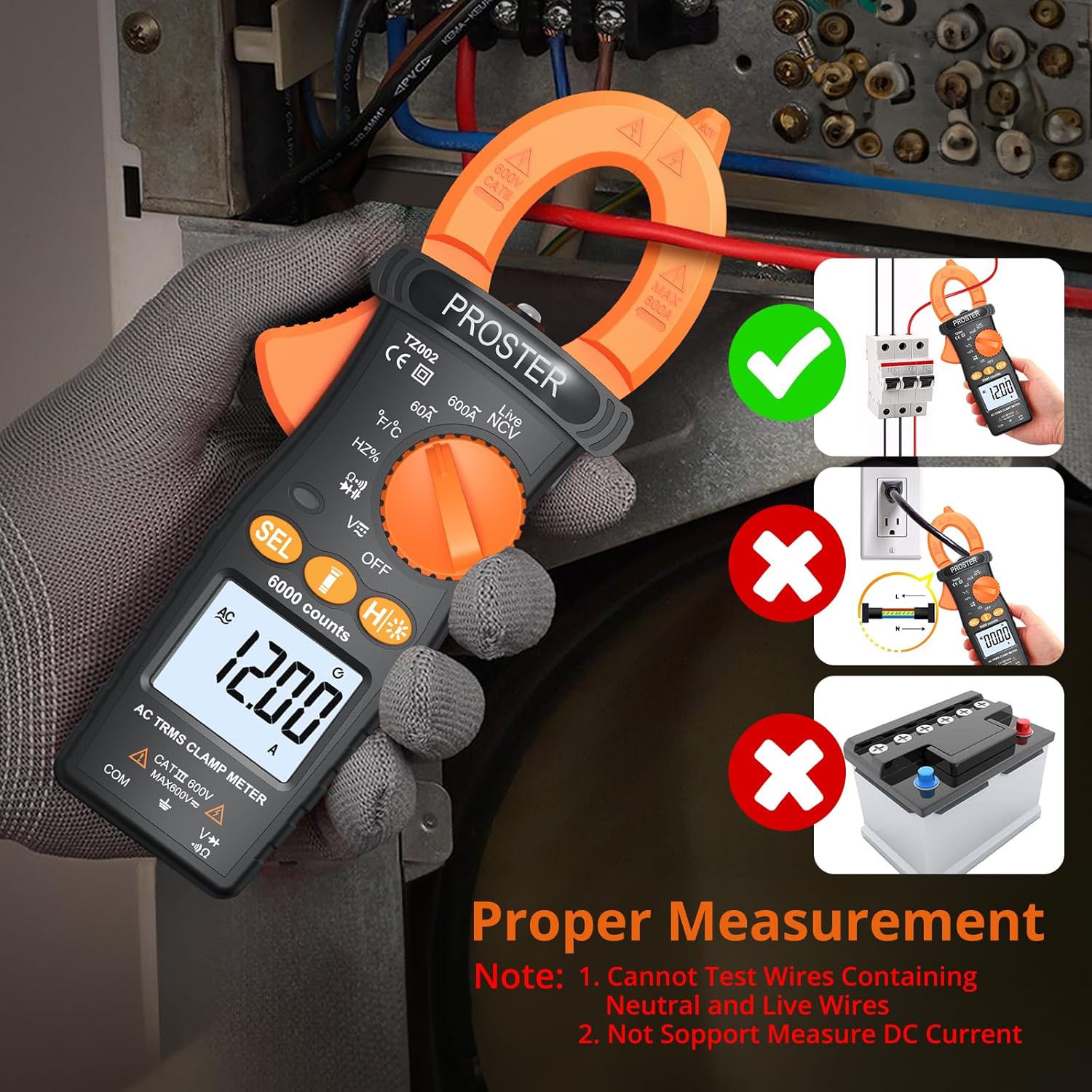
6.2 AC Current Measurement
This function allows measurement of AC current without breaking the circuit, by clamping the jaw around a single conductor.
- Turn the rotary dial to the '60A' or '600A' AC current range.
- Open the clamp jaw by pressing the trigger.
- Enclose only one conductor (live or neutral) within the clamp jaw. Do not clamp around multiple conductors (e.g., a power cord containing both live and neutral wires), as this will result in an inaccurate zero reading due to opposing magnetic fields.
- Read the AC current value on the LCD display.

6.3 AC/DC Voltage Measurement
To measure voltage, connect the test leads to the meter and the circuit.
- Insert the red test lead into the 'VΩHz' input jack and the black test lead into the 'COM' input jack.
- Turn the rotary dial to the 'V~' (AC Voltage) or 'V=' (DC Voltage) position. Use the 'SEL' button to switch between AC and DC if needed.
- Connect the test probes in parallel across the circuit or component to be measured.
- Read the voltage value on the LCD display.
6.4 Resistance Measurement
Measure resistance of components when the circuit is de-energized.
- Insert the red test lead into the 'VΩHz' input jack and the black test lead into the 'COM' input jack.
- Turn the rotary dial to the 'Ω' position.
- Connect the test probes across the component whose resistance is to be measured.
- Read the resistance value on the LCD display.
6.5 Capacitance Measurement
Measure capacitance of capacitors after ensuring they are fully discharged.
- Insert the red test lead into the 'VΩHz' input jack and the black test lead into the 'COM' input jack.
- Turn the rotary dial to the 'Capacitance' position (often shared with other functions, use 'SEL' to select).
- Connect the test probes across the capacitor.
- Read the capacitance value on the LCD display.
6.6 Frequency and Duty Cycle Measurement
Measure the frequency and duty cycle of AC signals.
- Insert the red test lead into the 'VΩHz' input jack and the black test lead into the 'COM' input jack.
- Turn the rotary dial to the 'Hz%' position.
- Connect the test probes across the signal source.
- Read the frequency (Hz) or duty cycle (%) value on the LCD display. Use 'SEL' to toggle between them.
6.7 Temperature Measurement
Use the included K-type thermocouple to measure temperature.
- Turn the rotary dial to the '°C/°F' position.
- Insert the K-type thermocouple into the input jacks, observing polarity.
- Place the tip of the thermocouple on or near the object whose temperature is to be measured.
- Read the temperature value on the LCD display. Use 'SEL' to switch between Celsius and Fahrenheit.
6.8 Non-Contact Voltage (NCV) Measurement
The NCV function detects the presence of AC voltage without physical contact, enhancing safety.
- Turn the rotary dial to the 'NCV' position.
- Move the top end of the clamp meter (where the NCV sensor is located) close to the conductor or outlet.
- The meter will beep and the LED indicator will flash, with the display showing '---L' for lower voltage (100-160VAC) or '---H' for higher voltage (>160VAC), indicating the presence of AC voltage.

6.9 Continuity Test
Checks for an open or closed circuit.
- Insert the red test lead into the 'VΩHz' input jack and the black test lead into the 'COM' input jack.
- Turn the rotary dial to the 'Ω' position and press 'SEL' until the continuity symbol (a speaker icon) is displayed.
- Connect the test probes across the circuit or component. A continuous beep indicates continuity (low resistance).
6.10 Diode Test
Tests the functionality of diodes.
- Insert the red test lead into the 'VΩHz' input jack and the black test lead into the 'COM' input jack.
- Turn the rotary dial to the 'Ω' position and press 'SEL' until the diode symbol is displayed.
- Connect the red probe to the anode and the black probe to the cathode of the diode. A forward voltage drop will be displayed. Reverse the probes; an open circuit ('OL') should be displayed.
6.11 Live Wire Detection
Identifies the live wire in an AC circuit.
- Turn the rotary dial to the 'Live' position.
- Insert the red test lead into the 'VΩHz' input jack. The black lead is not used for this function.
- Touch the red probe to the suspected live wire or terminal. The meter will beep and the indicator light will flash if a live wire is detected.
6.12 Backlight and Flashlight
The meter includes a backlight for the LCD display and a flashlight for illuminating the measurement area, useful in dimly lit environments.
- Press the 'H/*' button briefly to turn on/off the backlight.
- Press and hold the 'H/*' button to turn on/off the flashlight.

7. Maintenance
7.1 Cleaning
Wipe the meter's case with a damp cloth and mild detergent. Do not use abrasives or solvents. Keep the input terminals free of dirt and moisture.
7.2 Storage
When the meter is not in use for an extended period, remove the batteries to prevent leakage. Store the meter and its accessories in the provided soft pouch in a cool, dry place, away from direct sunlight and extreme temperatures.
7.3 Battery Replacement
Replace the batteries when the low battery indicator appears on the display to ensure accurate measurements. Refer to Section 5.1 for battery installation instructions.
8. Troubleshooting
If you encounter issues with your Proster Digital Clamp Meter, refer to the following common problems and solutions:
- No Display or Faint Display: Check battery installation and polarity. Replace batteries if they are low or depleted.
- Inaccurate Readings: Ensure the correct function is selected for the measurement. Verify test lead connections. For AC current, ensure only one conductor is within the clamp jaw. Check for external interference.
- 'OL' (Overload) Display: The measured value exceeds the selected range. If in auto-ranging mode, the value exceeds the meter's maximum capability for that function.
- No Continuity Beep: Ensure the circuit is de-energized. Check if the component is truly continuous.
- NCV Not Detecting Voltage: Ensure the NCV function is selected and the sensor is close enough to the AC voltage source.
9. Specifications
Technical specifications for the Proster Digital Clamp Meter TZ202:
| Feature | Specification |
|---|---|
| Product Dimensions | 8.66 x 3.86 x 2.17 inches |
| Item Model Number | TZ202 |
| Batteries | 3 AAA batteries (included) |
| Date First Available | July 23, 2024 |
| Manufacturer | Proster Trading Limited |
| ASIN | B0D9XT1TNL |
| Brand | Proster |
| Power Source | Battery Powered |
| Style | Digital Clamp Meter |
| Color | Orange & Black |
| Item Weight | 376 Grams (13.26 ounces) |
| Jaw Opening | Max 26mm |
| Display Count | 6000 Counts |
| Safety Rating | CAT III 600V |
10. Warranty and Support
Proster products are designed for reliability and performance. For warranty information, technical support, or service inquiries, please refer to the contact details provided with your purchase documentation or visit the official Proster website. Keep your purchase receipt as proof of purchase for warranty claims.


