1. Introduction
The KZYEE KM05 Power Circuit Probe Tester is a versatile 12V/24V automotive diagnostic tool designed to simplify electrical system troubleshooting. It functions as a digital volt meter, short/open breaker finder, and offers capabilities for AC/DC voltage, continuity, diode, and resistance testing. This manual provides essential information for the safe and effective use of your KM05 tester.
2. What's in the Box
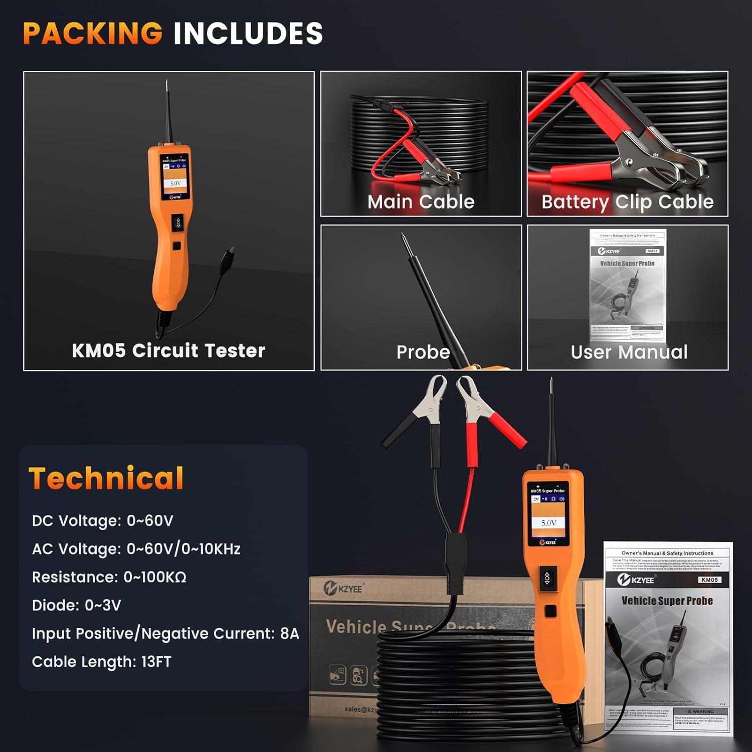
The KZYEE KM05 package typically includes the following components:
- 1x KZYEE KM05 Super Probe Circuit Tester
- 1x Extension Cable (13FT)
- 1x Battery Clip Cable
- 1x Probe Tip
- 1x User Manual
This image displays the KZYEE KM05 Power Circuit Probe Tester along with its accessories, including the main unit, extension cable, battery clip cable, probe tip, and the user manual, all neatly arranged.
3. Setup
To begin using your KZYEE KM05 Power Circuit Probe Tester, follow these steps:
- Connect to Power Source: The KM05 is powered by the vehicle's battery or an external 12V/24V battery. Connect the red battery clip to the positive (+) terminal and the black battery clip to the negative (-) terminal of the power source.
- Attach Probe: Securely attach the probe tip to the main unit.
- Initial Self-Test: Upon connection, the device will perform a self-test. Ensure the display illuminates and shows a stable reading.

This image illustrates the KZYEE KM05 Power Circuit Probe Tester, showing its main unit, the 13-foot extension cable, and the battery clip cables ready for connection to a vehicle's electrical system.
4. Operating Modes and Functions
The KM05 offers four primary testing modes and several diagnostic functions to assist in automotive electrical troubleshooting.
4.1. Four Powerful Modes

The KM05 features four distinct modes, selectable via the mode button, for precise diagnostics:
- DC Voltage Mode: Used to measure direct current voltage, identify power lines, and detect shorts.
- AC Voltage Mode: Used to measure alternating current voltage, useful for checking sensors and signal waves.
- Resistance Mode: Measures electrical resistance, ideal for testing wires, grounds, and fuses.
- Diode Mode: Verifies the direction and integrity of diodes within a circuit.
This image displays the four primary testing modes of the KZYEE KM05: DC Voltage, AC Voltage, Resistance, and Diode, showing how readings appear on the device's screen for each mode.
4.2. Component Activation

The KM05 allows for safe activation of components by sending power or ground through the probe tip. This function is useful for testing relays, lights, fuel injectors, fans, and blower motors directly on the vehicle without disassembly. Built-in circuit protection safeguards vehicle ECUs.

This image illustrates various vehicle components such as lights, dashboard, door mechanisms, wipers, AC accessories, and radiator fans, all of which can be activated and tested using the KM05 Power Circuit Probe Tester.

This image shows the KZYEE KM05 Power Circuit Probe Tester being used to activate a component (a car bulb) while held in hand, demonstrating its utility for testing components both on and off the vehicle.
4.3. Continuity & Signal Test

In Resistance mode, use the probe tip with a ground wire or auxiliary ground wire to test the continuity of wires and components. If the display shows "0.0Ω", the ground is good, the green LED will light up, and a beep will sound. The LCD will display "OL" if resistance is greater than 100KΩ. You can also verify continuity to ground or the battery using the power switch. If the circuit breaker trips, it indicates a secure connection with low resistance. The probe tip can pierce plastic insulation for testing without breaking connections.

For signal circuit testing, such as a MAP sensor, set the tool to AC Voltage mode. Connect the probe tip to chassis ground or the auxiliary ground lead. Connect a vacuum pump to the MAP sensor. Contact the probe tip to the MAP sensor positive terminal and observe the LCD readings, which should show a sine wave in normal conditions. Apply vacuum and check for changes. An abnormal LCD reading indicates a sensor problem.
4.4. LED Polarity Indicators

The KM05 features Red/Green LEDs to instantly indicate wire polarity. A red LED signifies a positive connection (power), a green LED indicates a negative connection (ground), and no light suggests an open circuit or break. This feature aids in quickly identifying shorts, bad grounds, or reverse connections without needing a separate multimeter.
This image highlights the KZYEE KM05's Red/Green Polarity LED indicators, showing a red light for positive and a green light for negative connections, alongside a visual representation of its overload protection feature.
4.5. Short Finder

To locate short circuits, which often manifest as a blown fuse or tripped electrical protection device:
- Remove the blown fuse from the fuse box.
- Use the probe tip to activate each contact of the fuse and power it up.
- The contact that causes the circuit breaker to trip indicates the short circuit.
- Note the wire's identification code or color, and trace the wire along the harness as far as possible. The tip probe can be inserted directly into the insulation.
This image provides a four-step visual guide on how to effectively follow and locate short circuits in a vehicle's electrical system using the KZYEE KM05 Power Circuit Probe Tester.
4.6. Trailer Light Test

To test trailer lights and connections:
- In DC voltage mode, clamp the auxiliary ground wire to the trailer ground line.
- Detect the contacts on the socket, then apply voltage to the tip of the probe.
- Check the trailer lights or other connections.
Note: If the circuit breaker trips, the contact may be grounded. Allow the breaker to cool for 15 seconds before resetting.
This image outlines a three-step procedure for testing trailer lights and their connections using the KZYEE KM05 Power Circuit Probe Tester, ensuring proper functionality.
4.7. Checking for Bad Ground Contacts

Probe the suspected ground wire or contact with the probe tip. If the green LED goes out, the red LED lights up, and the tool emits a beep, then this is not a true ground. If the circuit breaker trips, it is likely that the circuit has a good ground. However, be aware that large-current components, such as starter motors, can also cause the breaker to trip.
This image demonstrates how to check for bad ground contacts using the KZYEE KM05, explaining the visual and audible feedback provided by the device.
5. Applications
The KZYEE KM05 Power Circuit Probe Tester is suitable for a wide range of 6V-30V vehicle electrical systems, including cars, trucks, trailers, RVs, boats, motorcycles, buses, and heavy-duty trucks.

This image illustrates the wide range of applications for the KZYEE KM05, including testing turn signals, fuses, general circuits, switches, tail lights, and car bulbs.

This image showcases the broad applicability of the KZYEE KM05, demonstrating its use across various vehicle types such as cars, SUVs, trucks, ships, motorcycles, and buses.

This image reinforces that the KZYEE KM05 is not limited to cars but can be used on a diverse range of vehicles, including SUVs, ships, buses, motorcycles, heavy-duty trucks, and pickups.
6. Maintenance
To ensure the longevity and accurate performance of your KZYEE KM05 Power Circuit Probe Tester:
- Cleaning: Wipe the device with a soft, dry cloth after each use. Avoid using abrasive cleaners or solvents.
- Storage: Store the tester and its accessories in the provided case in a cool, dry place, away from direct sunlight and extreme temperatures.
- Cable Inspection: Regularly inspect the cables and probe tip for any signs of wear, cuts, or damage. Replace damaged components immediately to prevent electrical hazards and ensure accurate readings.
7. Troubleshooting
7.1. Overload Protection
The KM05 features an 8A auto-reset circuit breaker to protect both the vehicle and the tool from overloads. If the current exceeds the limit, the tool will disconnect power and emit an audible alarm. Allow the breaker to cool for approximately 15 seconds before resuming operation. This eliminates the need for fuse replacement.
This image illustrates the overload protection feature of the KZYEE KM05, showing how the device disconnects power and sounds an alarm when current limits are exceeded.
7.2. Device Does Not Turn On
- Check Power Connection: Ensure the battery clip cables are securely connected to a functional 12V or 24V vehicle battery or external power source. Verify that the red clip is on the positive terminal and the black clip is on the negative terminal.
- Battery Condition: Confirm that the vehicle battery or external battery has sufficient charge. The KM05 requires a working power source to operate.
- Cable Integrity: Inspect the battery clip cables and the main cable for any damage or breaks that might interrupt power flow.
8. Specifications

| Feature | Specification |
|---|---|
| Display | 1.77 inch TFT (160*128 DPI) |
| Supply Voltage | DC: 6V–35V |
| Operating Temperature | -20°C (-4°F) to 50°C (122°F) |
| Storage Temperature | -40°C (-40°F) to 65°C (149°F) |
| External Power | 12 or 24 V power provided via vehicle battery |
| Dimensions (L*W*H) | 8.85*1.77*1.38 inches |
| DC Voltage Range | 0-60V |
| AC Voltage Range | 0-60V/0-10KHz |
| Resistance Range | 0-100KΩ |
| Diode Range | 0-3V |
| Input Positive/Negative Current | 8A |
| Cable Length | 13FT |
This image provides a comprehensive overview of the KZYEE KM05's technical specifications, including its display type, voltage ranges, operating temperatures, power requirements, and physical dimensions.
9. Warranty and Support
The KZYEE KM05 Power Circuit Probe Tester comes with a 12-month warranty. For technical assistance or any inquiries, please contact KZYEE customer support:
- Email: support@kzyeetech.com
- Support: Lifetime technical support is provided.


