1. Introduction
The ANENG SZ308 Digital Multimeter is a versatile and essential tool designed for precise electrical measurements in both industrial and household applications. It accurately measures AC/DC Voltage, DC Current, Resistance, Continuity, and Diodes. This manual provides detailed instructions for the safe and effective operation of your multimeter, ensuring optimal performance and longevity.
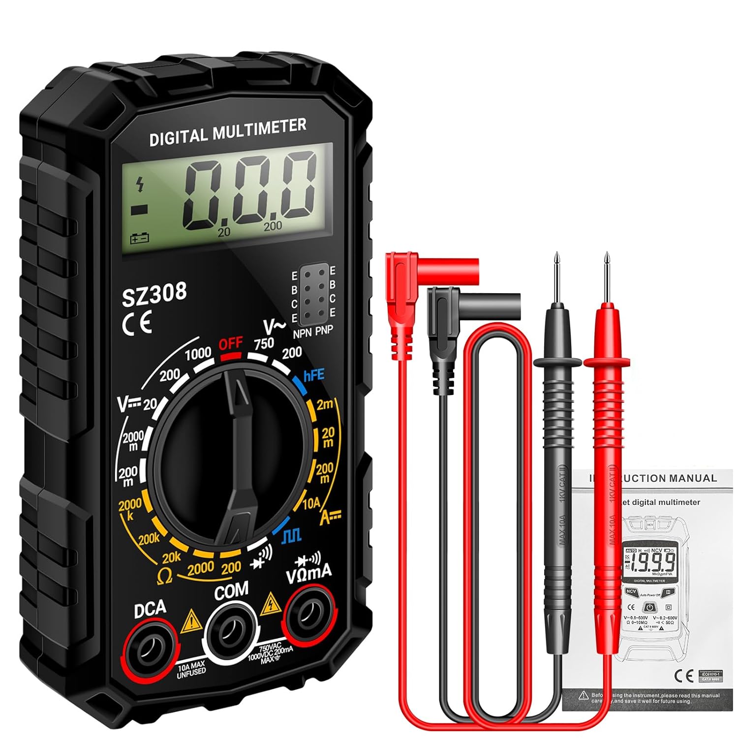
Figure 1: ANENG SZ308 Digital Multimeter and included test leads.
2. Features
- Multi-Purpose Measurement: Precisely measures AC/DC Voltage, DC Current, Resistance, Continuity, and Diodes.
- User-Friendly Display: Features a clear and easy-to-read screen for measurement values, settings, and modes.
- Ease of Use: 2000 Counts display, low battery indicator, and continuity buzzer. Equipped with two probes for accurate readings.
- Safety and Portability: Designed with safety features including anti-burn fuses, overload protection, and insulated probes. Compact and lightweight for easy transport.
- Additional Functions: Includes hFE Triode test and Square Wave output.

Figure 2: Key features of the ANENG SZ308 Multimeter.
3. What's in the Box
Your ANENG SZ308 Multimeter package includes the following items:
- 1 x ANENG SZ308 Multi Tester
- 2 x AAA Batteries (for initial use)
- 1 x Electrical Tester Kit (includes 4 connection sockets, 2 PVC cables, 2 copper needles, 2 U-shaped inserts, 2 meter pens, 2 alligator clips)
- 1 x Multimeter Test Lead Set
- 1 x Instruction Manual (this document)

Figure 3: Contents included with your ANENG SZ308 Multimeter.
4. Setup
4.1 Battery Installation
- Locate the battery compartment cover on the back of the multimeter.
- Slide or unclip the cover to open the compartment.
- Insert the provided 9V battery, ensuring correct polarity (+ and -).
- Close the battery compartment cover securely.

Figure 4: Proper battery installation for the multimeter.
4.2 Connecting Test Leads
The multimeter uses two test leads, typically red and black. The black lead is generally connected to the "COM" (common) jack, and the red lead is connected to the appropriate measurement jack based on the function you intend to use.
- Insert the black test lead into the "COM" (Common) jack.
- For most voltage, resistance, and diode measurements, insert the red test lead into the "VΩmA" jack.
- For high current (up to 10A) measurements, insert the red test lead into the "10A MAX UNUSED" jack.

Figure 5: Multimeter panel functions and test lead connection points.
5. Operating Instructions
This section details how to perform various measurements using your ANENG SZ308 Digital Multimeter. Always ensure the correct function is selected and test leads are properly connected before making any measurements.
Video 1: ANENG SZ308 Multimeter demonstration covering various measurement functions including DC current, DC voltage, resistance, continuity, diodes, square wave, triode, and AC voltage.
5.1 DC Current Measurement (DCA)
To measure DC current, the multimeter must be connected in series with the circuit. This means breaking the circuit and inserting the multimeter so that the current flows through it.
- Turn the rotary switch to the "DCA" range (e.g., 200m, 10A). For currents above 200mA, use the 10A range and connect the red lead to the "10A MAX UNUSED" jack.
- Break the circuit where you want to measure the current.
- Connect the red test lead to the positive side of the break and the black test lead to the negative side, completing the circuit through the multimeter.
- Read the current value on the display.
Refer to Video 1, segment 0:24 for DC Current measurement demonstration.
5.2 DC Voltage Measurement (DCV)
To measure DC voltage, connect the multimeter in parallel across the component or power source you wish to measure.
- Turn the rotary switch to the "DCV" range (e.g., 200m, 2V, 20V, 200V, 1000V). Select a range higher than the expected voltage.
- Connect the red test lead to the positive (+) point and the black test lead to the negative (-) point of the circuit or component.
- Read the voltage value on the display.
Refer to Video 1, segment 0:39 for DC Voltage measurement demonstration.
5.3 Resistance Measurement (Ω)
To measure resistance, ensure the circuit is de-energized before connecting the multimeter. Do not measure resistance on a live circuit.
- Turn the rotary switch to the "Ω" (Ohm) range (e.g., 200Ω, 2kΩ, 20kΩ, 200kΩ, 2MΩ). Select a range higher than the expected resistance.
- Connect the test leads across the component whose resistance you want to measure.
- Read the resistance value on the display.
Refer to Video 1, segment 0:56 for Resistance measurement demonstration.
5.4 Continuity Test (Buzzer)
The continuity test checks for a complete electrical path between two points. The multimeter will emit an audible beep if continuity is detected.
- Turn the rotary switch to the "Buzzer" or continuity symbol (often shared with diode test).
- Touch the test leads to the two points you want to check for continuity.
- If a continuous path exists (low resistance), the buzzer will sound.
Refer to Video 1, segment 1:14 for Buzzer (Continuity) test demonstration.
5.5 Diode Test
The diode test measures the forward voltage drop across a diode. This helps determine if a diode is functioning correctly.
- Turn the rotary switch to the "Diode" symbol (often shared with continuity).
- Connect the red test lead to the anode (positive) and the black test lead to the cathode (negative) of the diode.
- A healthy silicon diode will typically show a voltage drop between 0.5V and 0.8V. Reversing the leads should show an "OL" (Overload) reading.

Figure 6: Performing an hFE Triode test.
Refer to Video 1, segment 1:25 for Diode test demonstration.
5.6 Square Wave Output
The multimeter can generate a square wave signal for testing purposes.
- Turn the rotary switch to the "Square Wave" symbol.
- Connect the test leads to the input of the device you wish to test with the square wave.
- Observe the square wave output on the connected device (e.g., oscilloscope).
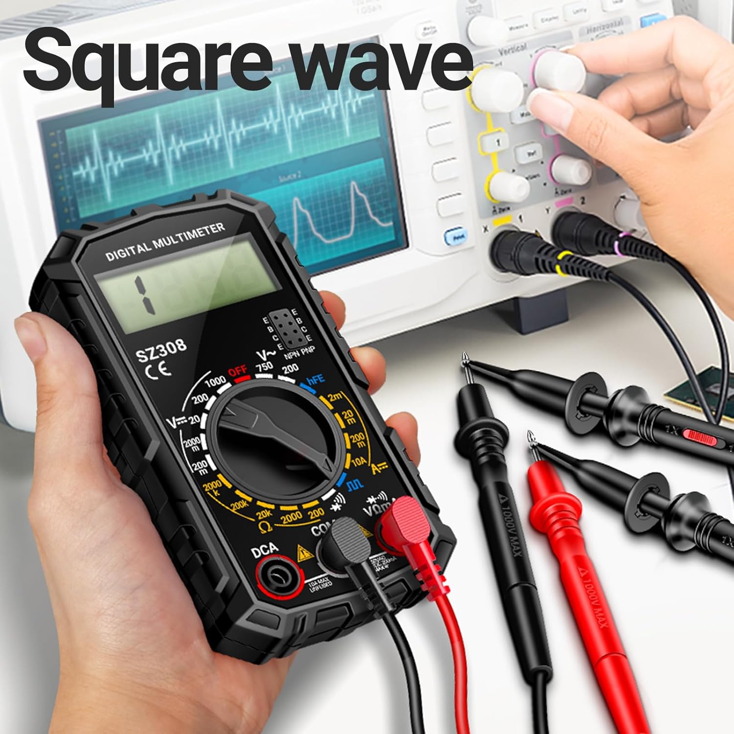
Figure 7: Using the multimeter for square wave output.
Refer to Video 1, segment 1:34 for Square Wave output demonstration.
5.7 Triode (hFE) Test
The hFE test measures the DC current gain of a transistor (bipolar junction transistor - BJT).
- Turn the rotary switch to the "hFE" position.
- Identify if the transistor is PNP or NPN type.
- Insert the transistor's emitter, base, and collector pins into the corresponding holes in the hFE socket on the multimeter.
- Read the hFE value on the display.
Refer to Video 1, segment 1:45 for Triode (hFE) test demonstration.
5.8 AC Voltage Measurement (ACV)
To measure AC voltage, connect the multimeter in parallel across the AC power source or component.
- Turn the rotary switch to the "ACV" range (e.g., 200V, 750V). Select a range higher than the expected voltage.
- Connect the test leads to the points where you want to measure the AC voltage. Polarity does not matter for AC voltage.
- Read the voltage value on the display.

Figure 8: Measuring AC voltage with the multimeter.
Refer to Video 1, segment 1:52 for AC Voltage measurement demonstration.
6. Specifications
| Attribute | Value |
|---|---|
| Model Number | SZ308 |
| Product Dimensions | 1.97 x 1.97 x 0.79 inches |
| Item Weight | 0.02 ounces (0.6 Grams) |
| Power Source | Battery Powered (1 x 9V battery included) |
| Color | Black |
| Manufacturer | ANENG |
| First Available Date | July 18, 2024 |

Figure 9: ANENG product range overview.
7. Maintenance
- Cleaning: Wipe the multimeter with a dry, soft cloth. Do not use abrasive cleaners or solvents.
- Storage: Store the multimeter in a cool, dry place away from direct sunlight and extreme temperatures.
- Battery Replacement: If the low battery indicator appears, replace the 9V battery promptly to ensure accurate readings. Follow the battery installation steps in Section 4.1.
- Fuse Replacement: If the multimeter fails to measure current or shows an "OL" reading on current ranges, the fuse may need replacement. Refer to the product's internal diagram or contact support for fuse specifications and replacement procedures. Always disconnect test leads and power before opening the device.
8. Troubleshooting
| Problem | Possible Cause | Solution |
|---|---|---|
| No display or dim display | Low or dead battery | Replace the 9V battery. |
| "OL" (Overload) reading | Measurement exceeds selected range; Open circuit (for continuity/current) | Select a higher range; Check circuit connections. |
| Incorrect readings | Incorrect function selected; Poor test lead connection; Damaged test leads | Verify rotary switch position; Ensure leads are firmly inserted; Inspect and replace damaged leads. |
| No continuity beep | Open circuit; Multimeter not in continuity mode | Check the circuit path; Ensure the rotary switch is on the continuity/buzzer setting. |
9. Warranty and Support
ANENG provides service and technical support for its products. For any questions, concerns, or warranty claims regarding your SZ308 Digital Multimeter, please refer to the contact information provided with your purchase or visit the official ANENG website for assistance.
Buy with confidence!


