
PowMr PS-3K-110V
Contents
PowMr 2400W Solar Inverter
Instruction Manual
1. Introduction
Thank you for choosing the PowMr 2400W Solar Inverter. This manual provides essential information for the safe and efficient installation, operation, and maintenance of your inverter. Please read this manual thoroughly before installation and operation to ensure proper usage and to prevent damage to the unit or injury to personnel. Keep this manual for future reference.
2. Safety Information
Always adhere to the following safety precautions to minimize risks of electric shock, fire, or injury.
- Installation must be performed by qualified personnel.
- Ensure all wiring is correctly polarized and securely connected.
- Do not disassemble the inverter. There are no user-serviceable parts inside.
- Keep the inverter away from flammable materials, moisture, and direct sunlight.
- Ensure adequate ventilation around the unit to prevent overheating.
- Disconnect all power sources (PV, battery, AC input) before performing any maintenance or wiring.
3. What's in the Box
Upon unpacking, please verify that all items listed below are included and undamaged:
- The unit x 1 (PowMr 2400W Solar Inverter)
- Instruction Manual x 1
- Communication cable x 1
- Software CD x 1
4. Product Overview
The PowMr 2400W Solar Inverter is a pure sine wave inverter with a built-in 50A PWM charge controller, designed for converting 24VDC to 110V/120VAC. It features full digital voltage and current double closed-loop control and advanced SPWM technology for high charging efficiency and reliable power output. This inverter is suitable for various applications, including homes and RVs, and is compatible with 24V lead-acid batteries (FLD, SLA, AGM, Gel).
Key Features:
- 2400W Pure Sine Wave Inverter (24VDC to 110V/120VAC)
- Integrated 50A PWM Charge Controller
- High charging efficiency (up to 95%)
- Multiple charging modes: solar, utility priority, solar priority, utility hybrid charging
- Three output modes: PV priority, Utility priority, Inverter priority
- LCD screen and 3 LED indicators for system data display
- Comprehensive protection functions: short circuit, over-voltage, under-voltage, overload, reverse polarity
- Suitable for 24V Lead-Acid (Flooded, SLA, AGM, Gel) batteries
Product Visuals:

Figure 4.1: Front view of the PowMr 2400W Solar Inverter, showing the display and control buttons.

Figure 4.2: Dimensions and key specifications of the 2.4KW Pure Sine Wave Inverter.

Figure 4.3: Illustration of multiple battery compatibility, including Flooded, AGM, Gel, and Sealed Lead Acid Batteries.
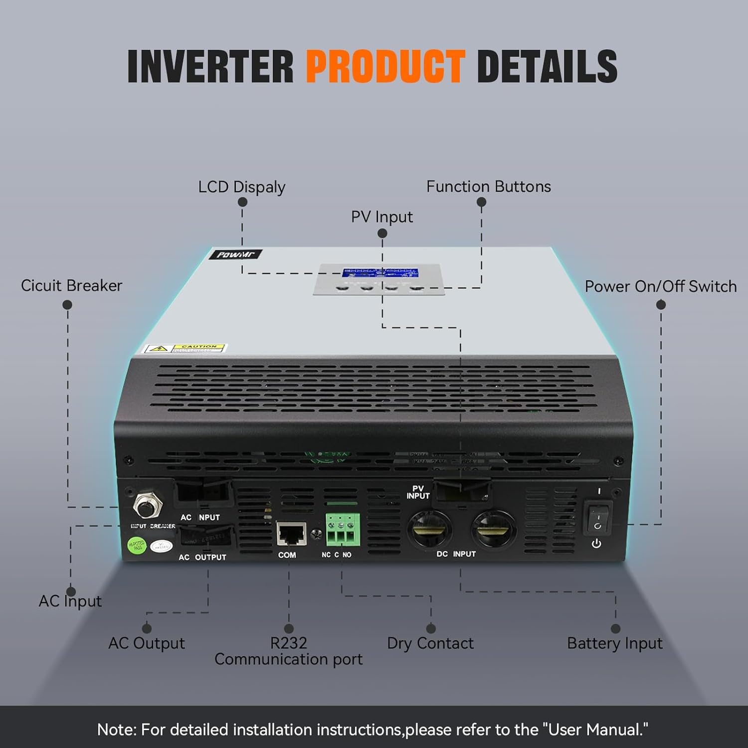
Figure 4.4: Diagram showing the four charging modes (Solar First, Utility First, Solar and Utility, Only Solar) and three load output working modes (Utility First, Solar First, SBU First).

Figure 4.5: Detailed view of the inverter's connections and components, including LCD display, function buttons, circuit breaker, AC input/output, R232 communication port, Dry Contact, PV input, DC input, and Power On/Off Switch.
Unboxing Video:
Video 4.1: An unboxing video of the PowMr 2400W Solar Inverter, showcasing the physical appearance and initial presentation of the product.
5. Setup
5.1 Pre-installation Checks
- Ensure the installation site is dry, well-ventilated, and free from direct sunlight or excessive dust.
- Verify that the battery voltage matches the inverter's requirements (24VDC).
- Confirm that all cables are of appropriate gauge for the expected current and are in good condition.
5.2 Mounting the Inverter
The inverter should be mounted vertically on a sturdy surface. Ensure there is sufficient clearance around the unit for proper airflow and heat dissipation. Use appropriate mounting hardware for your wall type.
5.3 Wiring Connections
All wiring should be performed by a qualified electrician to ensure safety and compliance with local electrical codes.
- Battery Connection: Connect the 24V battery bank to the DC input/Battery input terminals. Ensure correct polarity (+ to + and - to -).
- PV Input Connection: Connect your solar panel array to the PV input terminals. Observe the maximum PV array open circuit voltage (80V) and current limits.
- AC Input Connection: Connect the utility grid (110V-120V AC) to the AC input terminals.
- AC Output Connection: Connect your AC loads (appliances) to the AC output terminals.
- Communication Cable: Connect the communication cable between the inverter and your computer for monitoring and configuration using the provided software.
- Dry Contact: If applicable, connect external devices to the dry contact terminals for remote control or signaling.
Caution: Double-check all connections before powering on the unit to prevent damage.
6. Operating the Inverter
6.1 Powering On/Off
- To power on, ensure all connections are secure, then switch on the DC input breaker (if present), followed by the AC input breaker (if connected to grid), and finally the inverter's power switch.
- To power off, reverse the sequence: turn off the inverter's power switch, then the AC input breaker, and finally the DC input breaker.
6.2 LCD Display and Indicators
The LCD screen provides real-time system data and operating status. The three LED indicators (AC/INV, CHG, FAULT) provide quick status updates:
- AC/INV: Indicates AC input status or inverter operation.
- CHG: Indicates charging status.
- FAULT: Indicates a system fault or error.
6.3 Function Buttons
Use the ESC, UP, DOWN, and ENTER buttons to navigate through the LCD menu, view system parameters, and configure settings.
6.4 Charging Modes
The inverter supports four selectable charging modes:
- Solar Priority: Solar power is the primary charging source. Utility power is used only when solar power is insufficient.
- Utility Priority: Utility power is the primary charging source. Solar power is used only when utility power is unavailable.
- Solar and Utility: Both solar and utility power are used simultaneously for charging.
- Only Solar: Only solar power is used for charging.
6.5 Output Modes
Three output modes can be configured to meet different application needs:
- PV Priority: Solar power is the primary source for loads. Utility power is used as a backup.
- Utility Priority: Utility power is the primary source for loads. Inverter (battery/solar) power is used as a backup.
- Inverter Priority (SBU Mode): Battery/solar power is the primary source for loads. Utility power is used as a backup when battery voltage is low.
7. Maintenance
Regular maintenance ensures the longevity and optimal performance of your inverter.
- Cleaning: Periodically clean the exterior of the inverter with a dry cloth. Ensure ventilation openings are free from dust and debris. Do not use liquid cleaners.
- Connection Checks: Annually inspect all wiring connections for tightness and corrosion. Re-tighten if necessary.
- Battery Maintenance: Follow the battery manufacturer's guidelines for maintenance. Ensure battery terminals are clean and free of corrosion.
- Environmental Check: Ensure the installation environment remains within specified temperature and humidity ranges.
8. Troubleshooting
If the inverter is not operating correctly, refer to the following common issues. For more detailed troubleshooting, consult the full user manual provided on the software CD or contact customer support.
| Problem | Possible Cause | Solution |
|---|---|---|
| Inverter not turning on | No DC input from battery; Battery voltage too low; Power switch off. | Check battery connections; Charge battery; Turn on power switch. |
| No AC output | Overload; Short circuit on output; Inverter fault. | Reduce load; Check for short circuits; Refer to fault codes on LCD. |
| Battery not charging | PV input too low/none; AC input unavailable (if utility charging); Charge controller fault. | Check solar panels/connections; Verify AC input; Consult manual for charge controller diagnostics. |
| Fault indicator (FAULT LED) is on | Various system errors (e.g., over-temperature, over-voltage, under-voltage, short circuit). | Check LCD for specific error code; Refer to manual's fault code section for resolution. |
9. Specifications
Detailed technical specifications for the PowMr 2400W Solar Inverter:
| Specification | Value |
|---|---|
| Rated Output Power | 2400W (3000VA) |
| Output Voltage | 110Vac/120Vac ±10% |
| Output Waveform | Pure Sine Wave |
| DC Input Voltage | 24VDC |
| Max. PV Array Open Circuit Voltage | 80VDC |
| PWM Charge Controller Current | 50A |
| Hybrid Charging Max Charger Current | 50A |
| Operating Temperature Range | 0-55°C |
| Product Dimensions (L x W x H) | 13.97 x 3.97 x 10.7 inches |
| Item Weight | 15.18 pounds |
| Recommended Battery Capacity | 100/200Ah (24V sealed lead acid or sealed Gel/AGM battery) |
10. Warranty and Support
The PowMr 2400W Solar Inverter comes with a manufacturer's warranty. Please refer to the warranty card included in your package or contact PowMr customer support for specific warranty terms and conditions.
For technical assistance, troubleshooting beyond this manual, or warranty claims, please contact PowMr customer support through their official website or the contact information provided with your purchase. Ensure you have your product model number (PS-3K-110V) and purchase details ready when contacting support.
Ask a question about this manual
Ask about setup, troubleshooting, compatibility, parts, safety, or missing instructions. Manuals+ will review the question and use this page’s manual context to help answer it.