1. Introduction
This manual provides essential information for the installation, operation, and maintenance of your Luqeeg 36V-52V Electric Cycle Controller with S966 Color Display Panel. This controller is designed for brushless motors, offering efficient power management and control for electric bicycles. Please read this manual thoroughly before installation and use to ensure proper function and safety.
2. Product Overview
The Luqeeg Electric Cycle Controller system includes a robust controller unit and an S966 Color Display Panel.
2.1 Key Features
- Wide Compatibility: Suitable for 36V1500W, 36V2000W, 48V1500W, 48V2000W, and 52V1500W brushless motors, with or without Hall sensors. Features a self-learning function for easy adaptation.
- Efficient Heat Dissipation: The controller's aluminum alloy casing features a groove design for excellent heat dissipation, protecting internal circuits and preventing thermal overload.
- XT60 Plug: Equipped with an XT60 plug, featuring an insulating plastic case designed to prevent burning in case of fire, enhancing battery safety.
- 3-Mode Controller with Learning Line: Includes a learning line feature to prevent motor reversal. If the motor reverses, connect the two learning lines temporarily for forward rotation.
- Speed Limit Line: Provides a speed limit line for easy manipulation of speed settings, contributing to a more stable and quieter ride. Disconnect the two speed limit lines to disengage the speed limit.
2.2 Components

Image 1: Overview of the Luqeeg Electric Cycle Controller and S966 Display Panel. This image shows both the controller unit with its various wire connections and the S966 color display panel.

Image 2: Close-up view of the S966 Color Display Panel. This image highlights the display interface, showing speed, battery level, error indicators, and various riding modes.

Image 3: The XT60 plug connection on the controller. This image illustrates the robust, insulated power connector designed for safety.
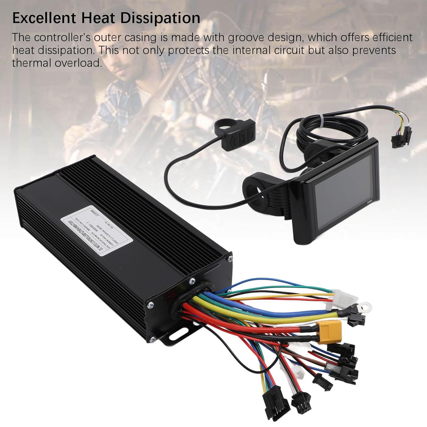
Image 4: Controller unit showcasing its heat dissipation design. The image highlights the grooved aluminum casing engineered for efficient cooling.
3. Specifications
| Feature | Detail |
|---|---|
| Item Type | Electric Cycle Controller Panel |
| Material | Aluminum Alloy, ABS |
| MOS Tube | 15 |
| Maximum Current | 40±1A |
| Communication Protocol | Protocol No.2 |
| Brake Input | Low Level |
| Panel Size | Approx. 100x61.5mm / 3.9x2.4in |
| Controller Size | Approx. 185x41x82mm / 7.3x1.6x3.2in |
| Item Weight | 966 g |
| Model Name | Luqeegraep5nmkoh |

Image 5: Detailed dimensions of the controller and S966 display panel. This image provides measurements for both components, aiding in installation planning.
4. Setup and Installation
Proper installation is crucial for the safe and efficient operation of your electric cycle. Due to the complexity of electrical connections, professional installation by a qualified technician is highly recommended.
Important Note: While a wiring diagram may be included, users have reported that it can be difficult to read or may not perfectly match the controller's actual wiring. Always verify connections carefully.
4.1 General Installation Steps (Consult a professional)
- Mount the Controller: Securely mount the controller unit to your electric bicycle frame in a location protected from water and physical damage, ensuring adequate airflow for heat dissipation.
- Mount the Display Panel: Attach the S966 display panel to your handlebars in a position that is easily visible and accessible while riding.
- Connect the Motor: Connect the motor phase wires (usually three thick wires) and Hall sensor wires (if applicable) from your brushless motor to the corresponding ports on the controller.
- Connect the Battery: Connect the battery's power output to the XT60 input on the controller. Ensure correct polarity.
- Connect the Display Panel: Plug the S966 display panel cable into the designated port on the controller.
- Connect Other Components: Connect throttle, brake levers (if equipped with cut-off sensors), and any other accessories (e.g., headlights, taillights) to their respective ports on the controller. Note: Some wiring, such as for headlights, may have reversed polarity (e.g., positive on black, negative on red). Verify with a multimeter if unsure.
- Self-Learning Function: After all connections are made, utilize the controller's self-learning function to optimize motor parameters. Refer to the specific instructions provided with the controller for this process, which typically involves connecting two "learning lines" temporarily.
- Speed Limit Line: If you wish to disengage the speed limit, disconnect the two designated speed limit lines.
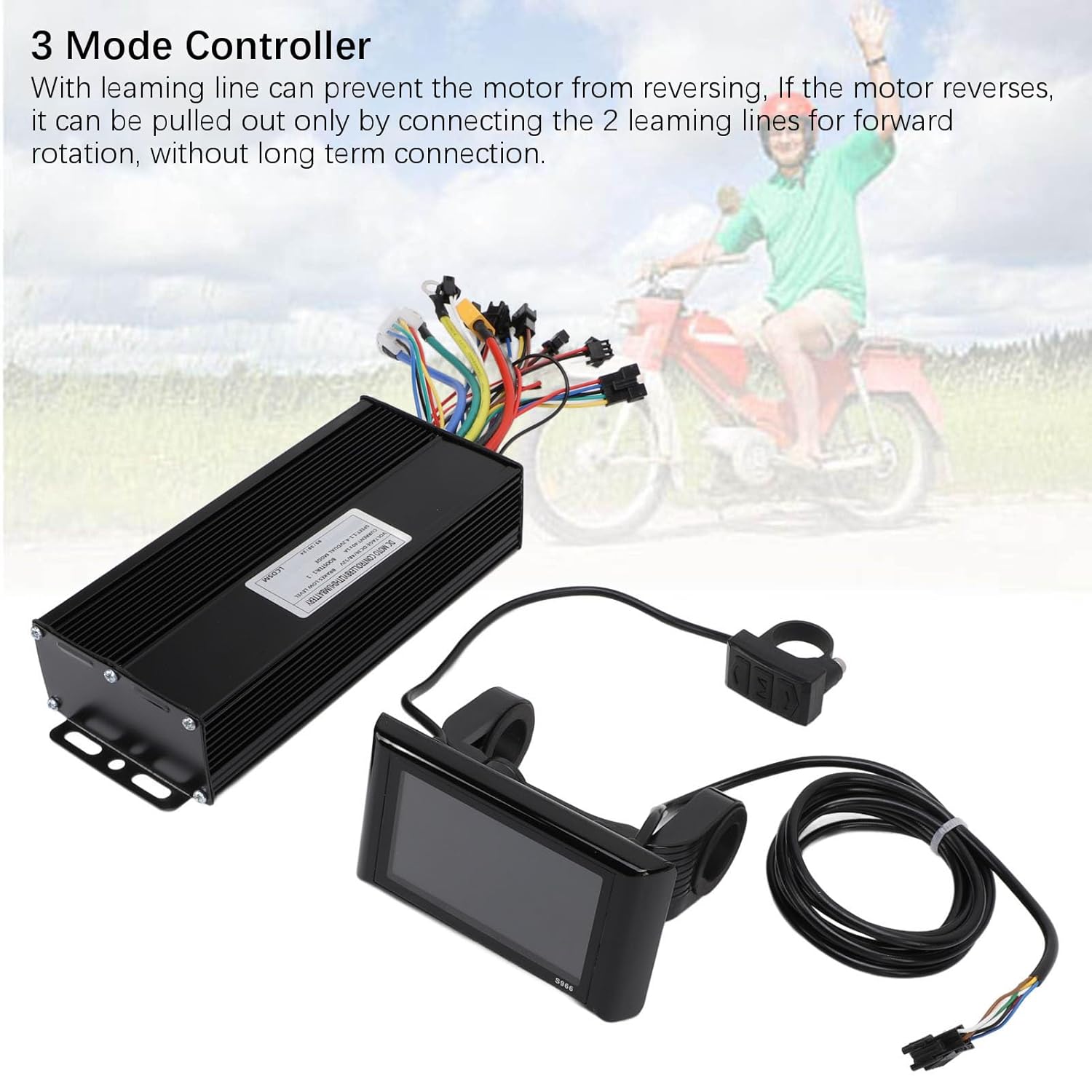
Image 6: Illustration of the 3-mode controller and its learning line feature. This image shows the controller with its various wire bundles, including the learning lines.
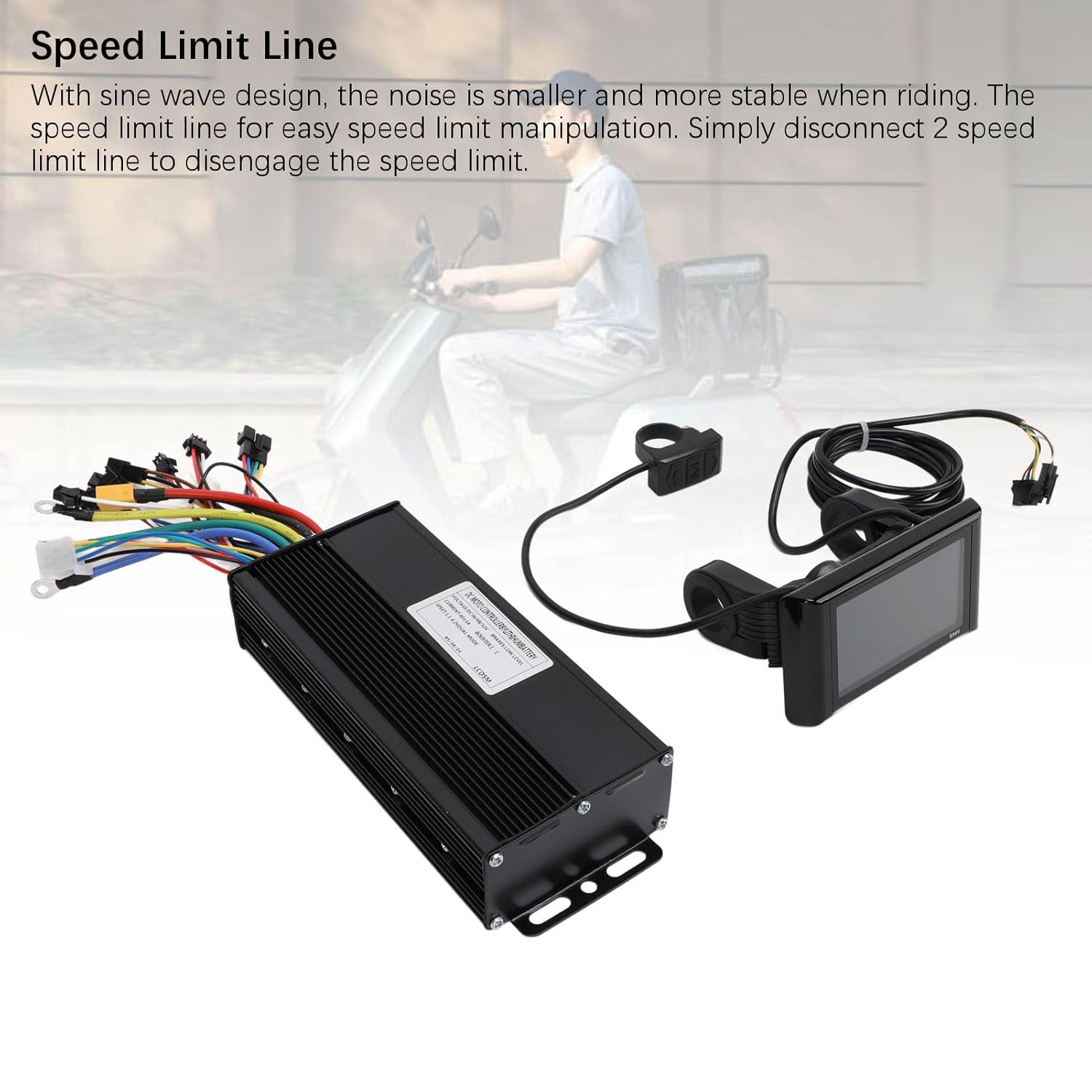
Image 7: Visual representation of the speed limit line feature. This image highlights the specific wires related to speed limit control.
5. Operating Instructions
The S966 Color Display Panel provides an intuitive interface for controlling and monitoring your electric cycle.
5.1 Basic Operation
- Power On/Off: Press and hold the power button on the S966 display panel to turn the system on or off.
- Speed Modes: The display typically shows different riding modes (e.g., ECO, STD, SPORT). Use the mode button to cycle through these options, adjusting power output and speed.
- Information Display: The S966 panel displays real-time information such as current speed, battery level, trip distance, total odometer, and error codes.
- Assistance Level: Adjust the pedal assist level using the up/down buttons to control the motor's assistance while pedaling.
5.2 Advanced Settings (S966 Display)
The S966 display panel has various programmable settings accessible through its menu.
Note: Detailed documentation for S966 menu settings may not be included with the product. Users may need to search for "S966 menu settings" online for comprehensive guidance on advanced configurations. Exercise caution when changing advanced settings, as incorrect configurations can affect performance or safety.
6. Maintenance
Regular maintenance ensures the longevity and reliable performance of your controller and display panel.
- Keep Dry: Protect the controller and display from water and excessive moisture. While designed for outdoor use, prolonged exposure to heavy rain or submersion can cause damage.
- Clean Regularly: Use a soft, damp cloth to clean the display panel and controller casing. Avoid abrasive cleaners or solvents.
- Inspect Connections: Periodically check all electrical connections for tightness and signs of corrosion or wear. Ensure all plugs are fully seated.
- Cable Management: Ensure all cables are properly routed and secured to prevent snagging or damage during riding.
- Avoid Physical Impact: Protect the components from drops or impacts, which can damage internal electronics or the display screen.
7. Troubleshooting
This section addresses common issues you might encounter. For complex problems, consult a qualified technician.
- No Power to Display/Motor:
- Check battery charge level.
- Verify all power connections, especially the XT60 plug, are secure.
- Ensure the display panel is correctly connected to the controller.
- Motor Not Responding or Running Erratically:
- Check motor phase wire and Hall sensor connections.
- Perform the self-learning function again if recently installed or if motor behavior changed.
- If the motor reverses direction, temporarily connect the two "learning lines" to correct it.
- Auto Cruise Control Engages Randomly:
- This can occur if the brake sensor is not properly set up or connected.
- If a brake sensor is not installed, the only way to disengage cruise control might be to momentarily cut power to the bike. Consider installing and properly configuring a brake sensor.
- Headlights/Accessories Not Working or Incorrectly Wired:
- Some wiring, such as for headlights, may have non-standard polarity (e.g., positive on black wire, negative on red wire). Always verify polarity with a multimeter before connecting.
- Error Codes on S966 Display:
- Refer to online resources for specific S966 error code meanings and troubleshooting steps, as these are not typically detailed in basic manuals.
8. Warranty and Support
For warranty information and technical support, please refer to the documentation provided at the time of purchase or contact Luqeeg customer service through the retailer where the product was acquired. Keep your proof of purchase for warranty claims.