
1. Introduction
This manual provides essential information for the safe and efficient operation of your Fafeicy Automatic Transfer Switch (ATS) 63A. This device is designed to ensure an uninterrupted power supply by automatically transferring the electrical load between different power sources, such as mains power, a generator, or an inverter. It features customizable settings for voltage thresholds and switching delays, making it suitable for various applications requiring reliable power management.
2. Safety Information
WARNING: Electrical shock hazard. Installation and maintenance should only be performed by qualified personnel. Failure to follow these instructions may result in serious injury or death.
- Always disconnect all power sources before installing or servicing the ATS.
- Ensure proper grounding of the device.
- Verify that the voltage and current ratings of the ATS match your electrical system requirements.
- Do not operate the device if it appears damaged.
- Keep the device away from moisture and extreme temperatures.
3. Product Overview
The Fafeicy Automatic Transfer Switch is a compact device designed for DIN rail mounting. It features an LED display for real-time voltage and current readings, along with control buttons for parameter adjustment.

Figure 3.1: Front view of the Fafeicy Automatic Transfer Switch ATS 63A. This image displays the overall design of the device, including the input and output terminals, the LED display for voltage and current, and the control buttons on the front panel.
3.1. Components and Display
The front panel includes an LED display that shows voltage (V) for each phase (L1, L2, L3) and the total current (A). Below the display are indicator lights for L1, L2, L3, and a 'Fault' indicator. Control buttons are provided for menu navigation and setting adjustments.
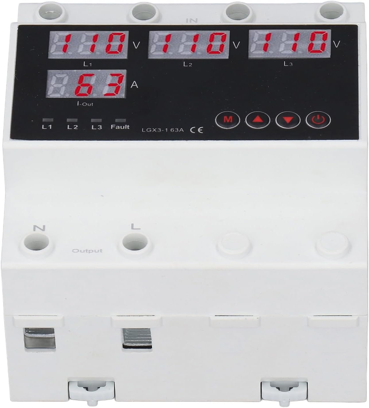
Figure 3.2: Detailed view of the LED display and control buttons. This image highlights the digital readouts for voltage and current, the phase indicator lights (L1, L2, L3), the 'Fault' indicator, and the 'M' (Menu), up, down, and power buttons for user interaction.
3.2. Dimensions

Figure 3.3: Physical dimensions of the Automatic Transfer Switch. The device measures approximately 95mm (3.74in) in height, 66mm (2.6in) in depth, and 90mm (3.54in) in width, indicating its compact size for installation.
4. Specifications
| Parameter | Value |
|---|---|
| Model | CHLT-GX2 |
| Material | Flame retardant PC |
| Power Terminals | N, L1, L2, L3 |
| Rated Operating Current | 63A |
| Maximum Operating Current | 80A |
| Auto Reclosing Delay (Ton) | 1-600s (Default: 30s) |
| Return Priority Stage Delay | 1-600s |
| Overvoltage Trip Delay | 0.1s (≥350V: 0.02s) |
| Undervoltage Trip Delay | 0.1s (≥350V: 0.02s) |
| Pollution Degree | 3 |
| Altitude | ≤2000m |
| Operating Temperature | -25℃ ~ +50℃ |
| Relative Humidity | ≤50% at 40℃ (non-condensing) |
| Wire Size | 0.5mm² - 1mm² |
| Installation | 35mm standard mounting rail |
| Item Weight | 13.7 ounces |
| Package Dimensions | 4.33 x 3.94 x 3.15 inches |
| Item Model Number | Fafeicyt2ggi16k7e-11 |
5. Setup and Installation
The ATS is designed for installation on a standard 35mm mounting rail. Ensure all power is disconnected before proceeding with installation.
5.1. Wiring Diagram
Connect the power sources and load according to the wiring diagram below. The device supports three-phase input (L1, L2, L3) and a neutral (N) connection. The output terminals connect to your electrical load.
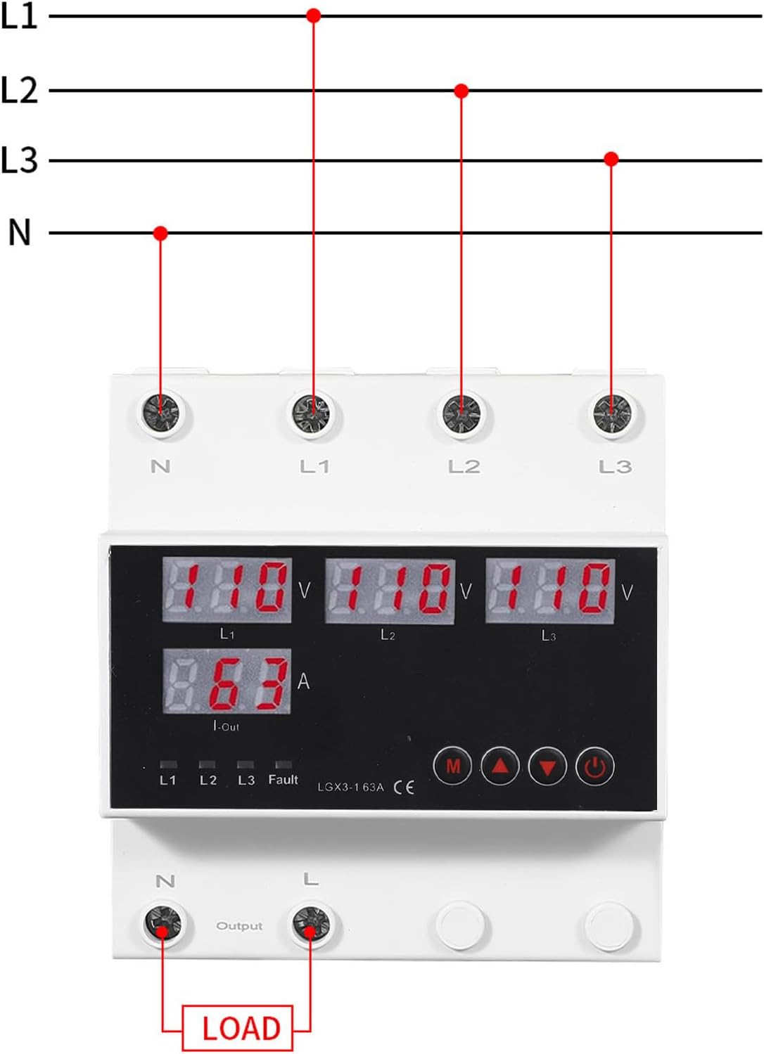
Figure 5.1: Wiring connections for the Automatic Transfer Switch. This diagram illustrates how to connect the neutral (N) and three phase lines (L1, L2, L3) from the power source to the input terminals, and the corresponding neutral and line outputs to the electrical load.
5.2. Application Diagram
The ATS can manage power transfer between various sources, such as public utility power, an inverter system, and a generator. The priority of these sources can be configured.

Figure 5.2: Typical application setup for the 3-Way Automatic Transfer Switch. This diagram visually represents how the ATS can be integrated into a power system to switch between Public Power (grid), an Inverter, and a Generator, allowing for flexible power source management.
6. Operating Instructions
The ATS allows for customizable settings to optimize power transfer based on your specific needs. The priority for power sources is typically set as L1 > L2 > L3, meaning L1 is the primary source, followed by L2, then L3.
6.1. Customizable Settings
- Power Source Priority: You can set the priority for mains power, generator, and inverter. The default priority is L1 > L2 > L3.
- Voltage Thresholds: Configure specific voltage thresholds for automatic switching in cases of under-voltage or over-voltage conditions.
- Switching Speed (Delay): The transfer time (Auto Reclosing Delay) is adjustable within a range of 1 to 600 seconds, with a default setting of 30 seconds. This controls how quickly the switch transfers the load to an alternative source.
- Reset Time: Adjustable parameter for the time before the system attempts to return to a preferred source after a fault is cleared.
- Overcurrent Parameters: Settings for detecting and reacting to overcurrent conditions.
6.2. Adjusting Parameters
Use the control buttons on the front panel (refer to Figure 3.2) to navigate the menu and adjust settings. The 'M' button typically accesses the menu, and the up/down arrows are used to change values. Consult the on-screen prompts for specific parameter adjustments.
7. Maintenance
The Fafeicy ATS is designed for reliable operation with minimal maintenance. However, periodic checks are recommended to ensure optimal performance and safety.
- Visual Inspection: Regularly inspect the device for any signs of physical damage, loose connections, or discoloration.
- Cleaning: Keep the device clean and free from dust and debris. Use a dry, soft cloth for cleaning. Do not use liquid cleaners.
- Connection Check: Periodically verify that all wiring connections are secure and tight.
8. Troubleshooting
If you encounter issues with your ATS, refer to the following common troubleshooting steps:
- No Power Display: Check the main power supply and all input connections. Ensure the device is properly wired and receiving power.
- No Automatic Transfer: Verify that the voltage thresholds and delay settings are correctly configured. Check the status of all connected power sources.
- Fault Indicator On: Identify the specific fault indicated on the display (if available) or through the indicator lights. This could be due to over/under voltage, overcurrent, or a wiring issue. Disconnect power and inspect connections.
- Incorrect Readings: Ensure all connections are secure. If readings appear consistently inaccurate, contact support.
If the problem persists after performing these checks, contact customer support for further assistance.
9. Warranty and Support
For warranty information and technical support, please refer to the documentation provided with your purchase or visit the official Fafeicy website. Keep your purchase receipt as proof of purchase for warranty claims.