
XYGStudy ESP32-S3-Touch-LCD-4.3B
Contents
User Manual: ESP32-S3 4.3inch Touch LCD Development Board
Model: ESP32-S3-Touch-LCD-4.3B
Brand: XYGStudy
1. Product Overview
The ESP32-S3 4.3inch Capacitive Touch Display Development Board Type B is a versatile microcontroller development board. It features an 800×480 resolution, 5-point capacitive touch display, and is powered by a 32-bit LX7 Dual-Core Processor with a frequency of up to 240MHz. This board supports WiFi and Bluetooth connectivity, making it ideal for a wide range of applications, especially those requiring Human-Machine Interface (HMI) development.
Key features include:
- Integrated 4.3-inch capacitive touch screen for smooth GUI programs like LVGL.
- Xtensa 32-bit LX7 dual-core processor, up to 240MHz.
- 2.4GHz Wi-Fi (802.11 b/g/n) and Bluetooth 5 (LE) support with onboard antenna.
- Built-in 512KB SRAM, 384KB ROM, with onboard 16MB Flash and 8MB PSRAM.
- 5-point touch control via I2C interface with interrupt support.
- Onboard voltage regulator supporting 7~36V wide range power supply.
- Onboard RTC chip and rechargeable battery for time data retention.
- Multiple peripheral interfaces: CAN, RS485, I2C, TF card slot, GH1.25 2P battery header, and digital isolated IO interfaces.

Figure 1.1: Front view of the ESP32-S3 4.3inch Touch LCD Development Board.
2. Package Contents
Upon opening the package, please verify that all components are present and undamaged.
- 1 x ESP32-S3-Touch-LCD-4.3B (with back wiring 16PIN screw terminal)
- 1 x 16PIN screw terminal for bottom wiring

Figure 2.1: Illustration of the package contents, showing the main board and the additional screw terminal.
3. Hardware Features and Pinout
The ESP32-S3-Touch-LCD-4.3B board integrates various components and interfaces to facilitate development. Understanding the layout and pinout is crucial for proper usage.

Figure 3.1: Detailed diagram of the ESP32-S3-Touch-LCD-4.3B board, highlighting key components and their functions.
Key Components and Interfaces:
- ESP32-S3N8R8: The SoC with WiFi and Bluetooth, operating up to 240MHz, integrated 8MB PSRAM and 16MB Flash.
- TF card slot: For external storage.
- USB Type-C port: For power and data communication.
- BOOT button: Press and hold while powering on for program burning.
- RESET button: Resets the board.
- Optocoupler isolation: For digital isolated IO interfaces.
- Touch panel connector: Connects the capacitive touch screen.
- 4.3inch display panel connector: Connects the LCD display.
- RS485 and CAN terminal resistors selection: Close by default.
- Battery power supply ON/OFF: Switch for battery power.
- 3.7V single lithium battery GH1.25 header: For connecting a rechargeable battery.
- Status Indicators:
- DONE: Lithium battery charging completed indicator.
- CHG: Lithium battery charging indicator.
- PWR: Power supply indicator (blinks and DONE lights when charging with DC power, off when battery switch is off).
- 7-36V DC power supply terminal: Wide range power input.
- I2C interface terminal: For I2C communication.
- VOUT pin output 5V/3.3V: Switchable via onboard resistor.
- CAN interface terminal: For CAN bus communication.
- RS485 interface terminal: For RS485 communication.
- Digital output: 5-36V, open-drain output, load: 450mA per channel (MAX).
- Input signal common terminal: NC: dry contact passive input. Connect to power supply positive: digital input low active, for NPN wet contact active input, 5-36V DC. Connect to power supply negative: digital input high active, for PNP dry contact active input, 5-36V DC.
- Digital input: 5-36V, supports passive / active input (NPN or PNP).
4. Setup and Wiring
The ESP32-S3-Touch-LCD-4.3B supports two primary wiring methods: bottom wiring and back wiring, offering flexibility for integration into various application scenarios such as DIN rail or embedded devices.
Figure 4.1: Illustration of the two supported wiring methods: Bottom Wiring and Back Wiring.
4.1 Power Supply Connection
Connect a 7-36V DC power supply to the designated power supply terminal (labeled 13 in Figure 3.1). Alternatively, a 3.7V single lithium battery can be connected to the GH1.25 2P battery header (labeled 11).
4.2 Peripheral Connections
The board supports various peripheral connections:
- I2C Interface: Connect I2C devices to the I2C interface terminal (labeled 14).
- CAN Interface: Connect CAN bus devices to the CAN interface terminal (labeled 16).
- RS485 Interface: Connect RS485 devices to the RS485 interface terminal (labeled 17).
- Digital I/O: Utilize the digital input (labeled 19) and digital output (labeled 18) terminals for various sensor and actuator connections. Refer to the detailed pinout for specific connections.
- TF Card: Insert a TF card into the TF card slot (labeled 2) for additional storage.

Figure 4.2: Diagram illustrating various peripheral connection options including I2C, CAN, RS485, and digital I/O.
5. Operating Instructions
5.1 Initial Power-Up
Once the power supply is connected, switch the battery power supply ON/OFF switch (labeled 10) to the ON position if using battery, or ensure external DC power is applied. The PWR indicator (labeled 12) should light up, indicating the board is receiving power.
5.2 Programming the Board
To upload firmware or programs to the ESP32-S3, connect the board to your computer via the USB Type-C port (labeled 3). Press and hold the BOOT button (labeled 4), then press the RESET button (labeled 5) and release both. This puts the board into programming mode. Use your preferred ESP-IDF or Arduino IDE environment to upload your code.
5.3 Using the Touch Display
The 4.3-inch capacitive touch display supports 5-point touch control. Applications developed using frameworks like LVGL can leverage this touch functionality for interactive user interfaces. The display offers excellent performance and a 160° wide viewing angle.

Figure 5.1: Demonstration of the 5-point capacitive touch functionality for flexible operation and smooth multi-point UI interaction.
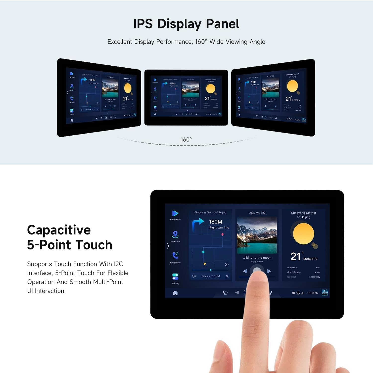
Figure 5.2: The IPS display panel provides excellent display performance with a 160° wide viewing angle.
5.4 Application Scenarios
This development board is highly suitable for Human-Machine Interface (HMI) applications, allowing for the transformation of information into a user-friendly format. It also supports LVGL GUI development, providing a robust graphics library for creating embedded GUIs with beautiful visual effects and low memory requirements.

Figure 5.3: Examples of application scenarios, including HMI development and LVGL GUI development.
6. Maintenance
To ensure the longevity and optimal performance of your ESP32-S3-Touch-LCD-4.3B development board, please follow these maintenance guidelines:
- Cleaning: Gently wipe the display and board surfaces with a soft, dry, lint-free cloth. Avoid using abrasive cleaners, solvents, or aerosol sprays.
- Storage: Store the board in a cool, dry environment, away from direct sunlight, extreme temperatures, and high humidity. Use anti-static bags if storing for extended periods.
- Handling: Always handle the board by its edges to avoid touching sensitive components. Use anti-static precautions (e.g., anti-static wrist strap) when working with the board to prevent electrostatic discharge (ESD) damage.
- Power Supply: Ensure the power supply voltage is within the specified 7-36V DC range. Incorrect voltage can damage the board.
- Connections: Periodically check all wiring connections to ensure they are secure and free from corrosion.
7. Troubleshooting
This section provides solutions to common issues you might encounter with your development board.
| Problem | Possible Cause | Solution |
|---|---|---|
| Board does not power on (PWR LED off). | No power supply, incorrect voltage, or battery switch off. | Verify power supply connection and voltage (7-36V DC). Ensure battery switch is ON if using battery. Check USB-C cable if powering via USB. |
| Cannot upload code to ESP32-S3. | Board not in programming mode, incorrect drivers, or faulty USB cable. | Ensure you press and hold BOOT, then press RESET, then release both to enter programming mode. Install necessary USB drivers. Try a different USB cable and port. |
| Display is blank or not responding. | Display not properly connected, software issue, or power problem. | Check the 4.3inch display panel connector (labeled 8). Ensure your code initializes the display correctly. Verify power supply. |
| Touch screen not responding. | Touch panel connector loose, I2C communication issue, or software not handling touch input. | Check the touch panel connector (labeled 7). Verify I2C communication in your software. Ensure touch input handling is correctly implemented in your code. |
| Wi-Fi or Bluetooth connectivity issues. | Incorrect firmware, interference, or antenna issue. | Ensure your firmware includes correct Wi-Fi/Bluetooth configurations. Minimize interference from other devices. The board has an onboard antenna, ensure it's not obstructed. |
8. Technical Specifications
| Feature | Specification |
|---|---|
| Model Number | ESP32-S3-Touch-LCD-4.3B |
| Processor | Xtensa 32-bit LX7 Dual-Core Processor |
| Main Frequency | Up to 240MHz |
| Wireless Connectivity | 2.4GHz Wi-Fi (802.11 b/g/n), Bluetooth 5 (LE) |
| SRAM | 512KB |
| ROM | 384KB |
| Onboard Flash | 16MB |
| Onboard PSRAM | 8MB |
| Display Type | 4.3inch Capacitive Touch Display |
| Resolution | 800×480 pixels, 65K color |
| Touch Points | 5-point touch with interrupt support |
| Power Supply | 7~36V DC (wide range), 3.7V single lithium battery via GH1.25 header |
| Interfaces | USB Type-C, CAN, RS485, I2C, TF card slot, Digital Isolated IO |
| RTC Chip | Onboard, with rechargeable battery support |
| Dimensions | Refer to Outline Dimensions diagram (Figure 8.1) |
Figure 8.1: Outline dimensions of the ESP32-S3-Touch-LCD-4.3B board in millimeters.
9. Warranty and Support
This product is manufactured by XYGStudy. For specific warranty information, please refer to the terms and conditions provided at the time of purchase or contact your retailer.
For technical support, user guides, resources, or any inquiries regarding the ESP32-S3-Touch-LCD-4.3B, please contact XYGStudy directly via message. They will provide necessary attachments and assistance.
You can also refer to the official documentation and community forums for ESP32-S3 development for extensive resources and peer support.
Documents and downloads
Ask a question about this manual
Ask about setup, troubleshooting, compatibility, parts, safety, or missing instructions. Manuals+ will review the question and use this page’s manual context to help answer it.