1. Safety Information
Read and understand all safety warnings and instructions before operating this equipment. Failure to follow these instructions may result in serious injury or death.
- Qualified Personnel Only: Only trained and authorized personnel should operate this lift.
- Proper Installation: Ensure the lift is installed on a level, solid concrete foundation capable of supporting the lift's weight and maximum load.
- Load Capacity: Do not exceed the maximum rated load capacity of 12,000 lbs (5443 kg).
- Vehicle Placement: Always center the vehicle on the lift arms and ensure proper weight distribution. Use appropriate adapters for different vehicle types.
- Safety Locks: Always engage the safety locks before working under the vehicle. Never work under a lift that is not fully engaged on its safety locks.
- Clear Area: Keep the area around the lift clear of obstructions, tools, and personnel during operation.
- Regular Inspections: Perform daily inspections of the lift for any signs of wear, damage, or malfunction. Refer to the Maintenance section for details.
- Emergency Stop: Familiarize yourself with the location and operation of the emergency stop button.
2. Product Overview
The APlusLift AP-12SR is a heavy-duty 12,000 LB two-post overhead clear floor car lift designed for professional automotive service. It features a robust alloy steel construction and a hydraulic lifting system.
Key Features:
- 12,000 LB (5443 kg) lifting capacity.
- Overhead clear floor design for unobstructed workspace.
- Single point safety lock release system.
- Extra wide 109" drive-through clearance.
- Screw-up pads with 3" and 6" tall truck adapters included.
- CE Certified structure and hydraulic system.
- Robotically welded structure with durable powder-coated finish.
- Direct drive cylinders, eliminating chains or pulleys.
Components:
The AP-12SR lift consists of the following main components:
- Two Vertical Columns (Power Side and Off Side)
- Cross Beam (Overhead)
- Lifting Carriages
- Lifting Arms (Triple-Telescoping Symmetrical Arms)
- Lift Pads with Screw-Up Adapters
- Hydraulic Power Unit
- Hydraulic Cylinders and Hoses
- Safety Lock System
- Anchor Bolts and Shims

Figure 2.1: Overview of the APlusLift AP-12SR Two Post Overhead Clear Floor Car Lift. This image shows the complete lift assembly with its two vertical columns, overhead cross beam, and lifting arms.
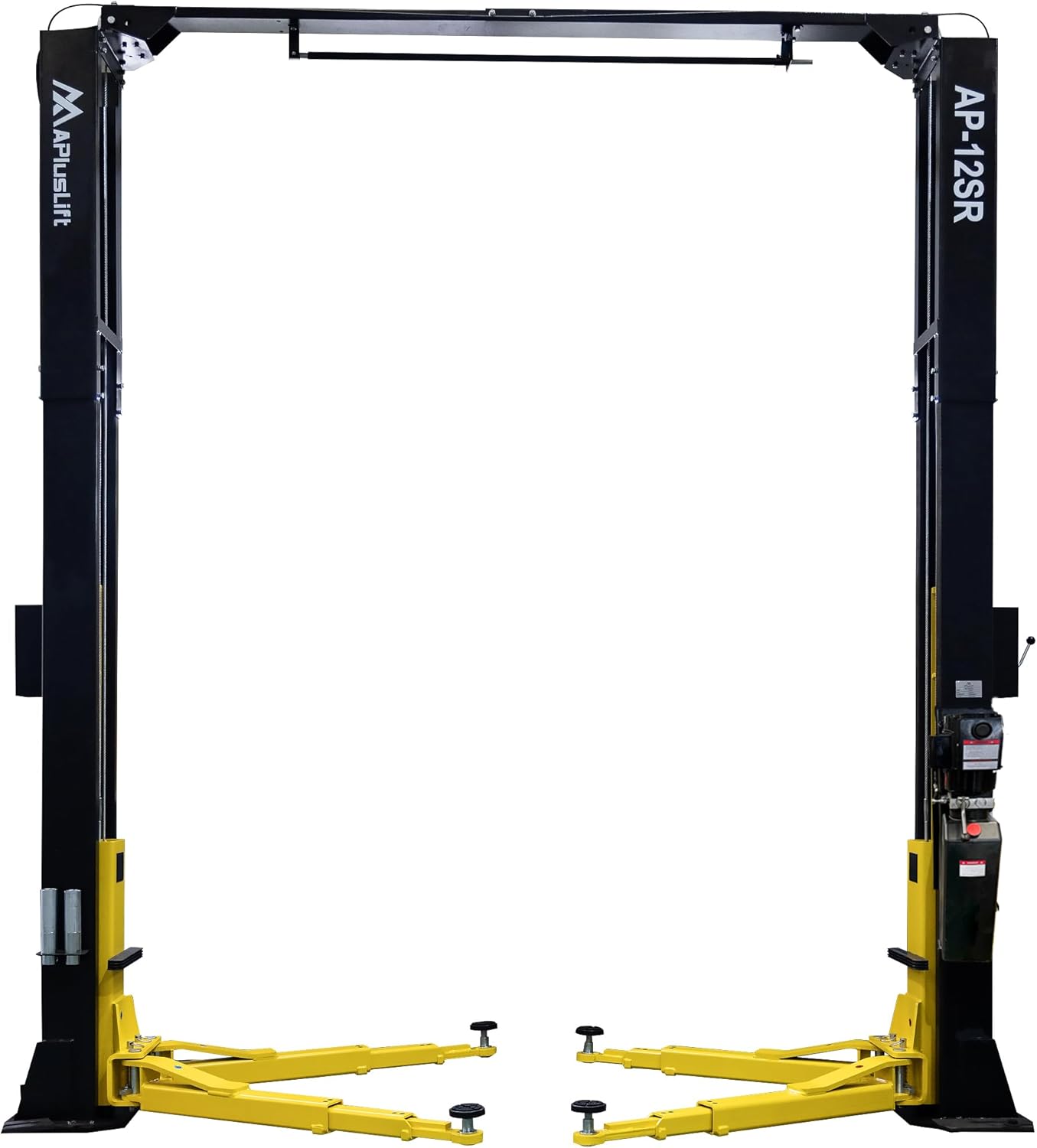
Figure 2.2: The APlusLift AP-12SR car lift with its lifting arms extended, demonstrating the full reach of the symmetrical arms.

Figure 2.3: Close-up view of the top section of an APlusLift AP-12SR column, showing the cable routing and structural connection points.

Figure 2.4: Detailed view of the hydraulic cylinder and equalization cables within the APlusLift AP-12SR lift column, essential for smooth and synchronized lifting.
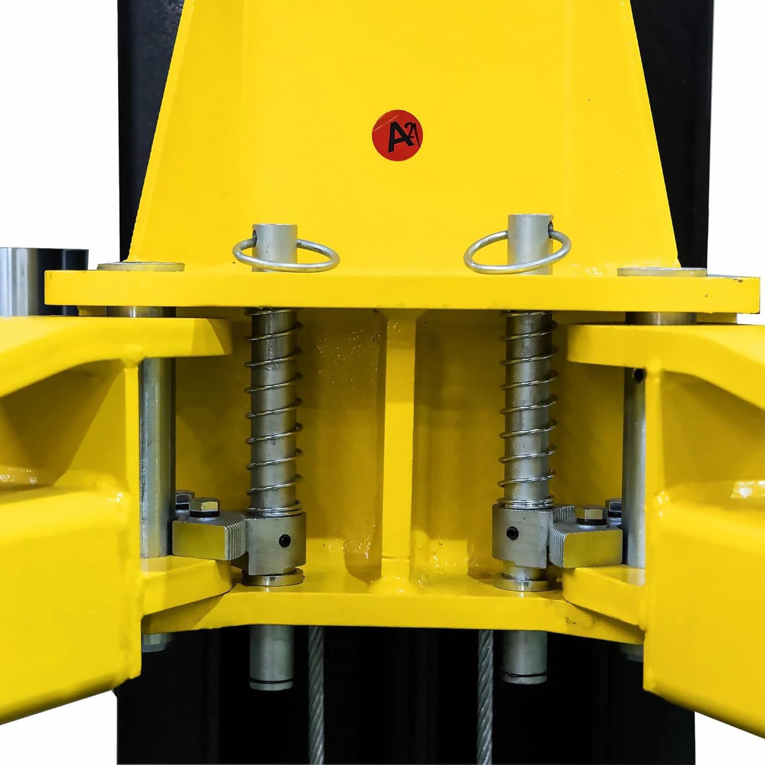
Figure 2.5: Close-up of the automatic arm locking gears on the APlusLift AP-12SR, which engage to secure the lifting arms in position.

Figure 2.6: Detail of the screw-up lift pad with its rubber top, providing adjustable height and secure contact with the vehicle's frame.

Figure 2.7: The included 3-inch and 6-inch tall truck adapters, which extend the reach of the lift pads for vehicles with higher ground clearance.

Figure 2.8: The robust base plate of an APlusLift AP-12SR column, showing the anchor points and a hydraulic line connection.
3. Specifications
| Specification | Value |
|---|---|
| Model | AP-12SR |
| Lifting Capacity | 12,000 lbs (5443 kg) |
| Lift Type | Two Post, Overhead Clear Floor |
| Drive Through Width | 109 inches |
| Maximum Lifting Height (with truck adapters) | 6'7" (79 inches) |
| Time to Full Rise | 75 seconds |
| Material | Alloy Steel |
| Certifications | CE Certified (Tested for 115% Dynamic Load, 150% Static Load) |
| Item Weight | 2500 pounds |
| Product Dimensions (L x W x H) | 150 x 25 x 165 inches |
| Included Components | AP-12SR 12000LB Two Post Overhead Clear Floor Car Lift, Screw-up pads, 3" and 6" Truck Adapters, Anchor Bolts, Shims |

Figure 3.1: Technical drawing showing key dimensions of the APlusLift AP-12SR lift, including overall height, width, and drive-through clearance.
4. Setup and Installation
Proper installation is critical for the safe and reliable operation of your APlusLift AP-12SR. It is highly recommended that installation be performed by qualified professionals.
4.1 Site Requirements:
- Foundation: A level concrete floor, minimum 4 inches thick, with a minimum compressive strength of 3000 PSI. The concrete must be cured for at least 28 days.
- Overhead Clearance: Sufficient overhead clearance is required for the lift's maximum height (165 inches / 13'9") plus the height of the vehicle being lifted.
- Power Supply: A dedicated electrical circuit suitable for the hydraulic power unit (typically 220V, single-phase, 30A). Consult the power unit's label for exact requirements.
- Space: Ensure adequate space around the lift for vehicle entry/exit, arm swing, and safe operation. Refer to the dimensional drawing in Section 3.
4.2 Unpacking and Inspection:
- Carefully unpack all components and check against the packing list.
- Inspect all parts for shipping damage. Report any damage immediately to the carrier and your supplier.
- Ensure all anchor bolts, shims, and small components are present.
4.3 Assembly Steps (General Overview):
This is a general guide. Always refer to the detailed installation manual provided with your lift for precise instructions and torque specifications.
- Position Columns: Carefully position the two columns according to the specified dimensions and ensure they are plumb and level.
- Anchor Columns: Drill holes and secure the columns to the concrete floor using the provided anchor bolts. Use shims as necessary to ensure columns are perfectly plumb.
- Install Overhead Beam: Lift and secure the overhead cross beam between the two columns.
- Install Carriages and Cables: Slide the lifting carriages onto the columns and route the equalization cables through the pulleys as per the diagram.
- Install Hydraulic Cylinders and Hoses: Install the hydraulic cylinders within the columns and connect the hydraulic hoses between the cylinders and the power unit.
- Mount Power Unit: Secure the hydraulic power unit to the designated column.
- Electrical Connection: Connect the power unit to the electrical supply. This step must be performed by a qualified electrician.
- Fill Hydraulic Fluid: Fill the power unit reservoir with appropriate hydraulic fluid (e.g., AW-32 or AW-46).
- Install Arms and Pads: Attach the lifting arms to the carriages and install the screw-up pads and truck adapters.
- Test and Adjust: Perform initial test cycles without a load to bleed air from the hydraulic system and verify proper operation of all components, especially the safety locks and equalization system. Adjust cable tension as needed.
5. Operating Instructions
Follow these steps for safe and effective operation of your APlusLift AP-12SR car lift.
5.1 Pre-Operation Checklist:
- Ensure the lift area is clear of personnel and obstructions.
- Verify that the lift is properly anchored and all components are secure.
- Check hydraulic fluid level.
- Inspect hydraulic hoses and fittings for leaks or damage.
- Confirm safety locks are functioning correctly.
5.2 Lifting a Vehicle:
- Position Vehicle: Drive the vehicle onto the lift, centering it between the columns. Ensure adequate clearance for the lifting arms.
- Position Arms: Swing the lifting arms into position under the vehicle's designated lifting points. Use the screw-up pads and truck adapters as needed to ensure solid contact. The automatic arm locking gears will engage.
- Raise Vehicle: Press and hold the "UP" button on the power unit. The lift will begin to raise.
- Engage Safety Locks: Raise the vehicle slightly past the desired working height, then lower it slowly until the safety locks engage with an audible click. This ensures the vehicle is resting securely on the mechanical locks, not just hydraulic pressure.
- Verify Stability: Gently shake the vehicle to confirm it is stable and securely supported on all four pads.
- Work Safely: You may now safely work under the vehicle.
5.3 Lowering a Vehicle:
- Clear Area: Ensure no tools, equipment, or personnel are under or around the vehicle.
- Raise Slightly: Press the "UP" button to raise the vehicle just enough to disengage the safety locks.
- Release Safety Locks: Pull the single point safety lock release handle to disengage both safety locks simultaneously.
- Lower Vehicle: Press and hold the "DOWN" lever/button on the power unit. The vehicle will begin to descend.
- Full Descent: Continue lowering until the arms are fully retracted and the vehicle is resting on the floor.
- Retract Arms: Swing the lifting arms clear of the vehicle.
- Drive Off: Carefully drive the vehicle off the lift.
6. Maintenance
Regular maintenance is essential to ensure the longevity and safe operation of your APlusLift AP-12SR.
6.1 Daily Checks:
- Inspect all cables and chains for wear, fraying, or damage.
- Check hydraulic hoses and fittings for leaks.
- Verify proper operation of safety locks and arm restraints.
- Ensure all fasteners (bolts, nuts) are tight.
- Check for any unusual noises during operation.
6.2 Monthly Checks:
- Lubricate all moving parts, including cables, pulleys, and arm pivots, with appropriate grease or oil.
- Check hydraulic fluid level and top off if necessary.
- Inspect anchor bolts for tightness. Re-torque if needed.
- Clean columns and carriages to prevent debris buildup.
6.3 Annual Checks:
- Drain and replace hydraulic fluid.
- Inspect all structural components for cracks, bends, or deformation.
- Check electrical connections for corrosion or damage.
- Have a qualified technician perform a thorough inspection and certification.
7. Troubleshooting
This section provides solutions to common issues you might encounter with your AP-12SR lift. For problems not listed here, contact APlusLift customer support.
| Problem | Possible Cause | Solution |
|---|---|---|
| Lift does not raise. | No power to power unit; Low hydraulic fluid; Motor malfunction; Electrical issue. | Check power supply and circuit breaker; Fill hydraulic fluid; Consult electrician or APlusLift support. |
| Lift raises slowly or unevenly. | Low hydraulic fluid; Air in hydraulic system; Clogged filter; Uneven cable tension. | Check and fill fluid; Bleed air from system (cycle lift up/down); Replace filter; Adjust cable tension. |
| Lift will not lower. | Safety locks engaged; Obstruction; Malfunctioning lowering valve. | Raise lift slightly to disengage locks, then release; Check for obstructions; Inspect/replace lowering valve. |
| Oil leaks. | Loose fittings; Damaged hose or seal. | Tighten fittings; Replace damaged components. |
| Excessive noise during operation. | Lack of lubrication; Loose components; Worn bearings/pulleys. | Lubricate all moving parts; Tighten fasteners; Inspect and replace worn parts. |
8. Warranty and Support
APlusLift provides comprehensive warranty coverage and customer support for the AP-12SR lift.
8.1 Warranty Information:
The APlusLift AP-12SR comes with an industry-leading 3-year warranty on parts. This warranty covers electrical and hydraulic components, ensuring reliable service.
For specific warranty terms and conditions, please refer to the warranty document included with your purchase or contact APlusLift directly.
8.2 Customer Support:
APlusLift is committed to providing exceptional customer service. Support is accessible via phone, text, chat, or email.
For technical assistance, parts inquiries, or warranty claims, please contact APlusLift customer support through their official channels. Refer to the contact information provided at the time of purchase or on the APlusLift website.
With nationwide warehouses, APlusLift ensures fast delivery and discounted pick-up options for parts and accessories.