
Introduction
This manual provides instructions for the installation and operation of the NR NIRIDER 1 Lead DT Wiring Harness Kit. This kit is designed to power and control auxiliary LED lights or other 12V devices up to 400W. It features a plug-n-play design for ease of use and includes essential components for safe operation.
What's in the Box
Verify that all components are present before beginning installation:
- 14.6ft 1 lead DT wiring harness
- Red indicator light rocker switch
- Plug-in style 40A relay
- 2pcs ATO style 15A fuses
- DT connector adaptor

Image: The complete NR NIRIDER 1 Lead DT Wiring Harness Kit, coiled and showing the rocker switch, relay, fuse, and DT connector.
Specifications
| Feature | Detail |
|---|---|
| Model | 1 Lead |
| Cable Length | 14.6 ft |
| Switch Type | Rocker Switch (On/Off) |
| Relay | Plug-in style 40A |
| Fuse Type | ATO style 15A (2 pcs included) |
| Input Voltage | 12-16V DC |
| Max Wattage | 400W |
| Wire Gauge | AWG 14 |
| Material | Nylon jacket |
| Waterproof Rating | IP67 (connectors) |
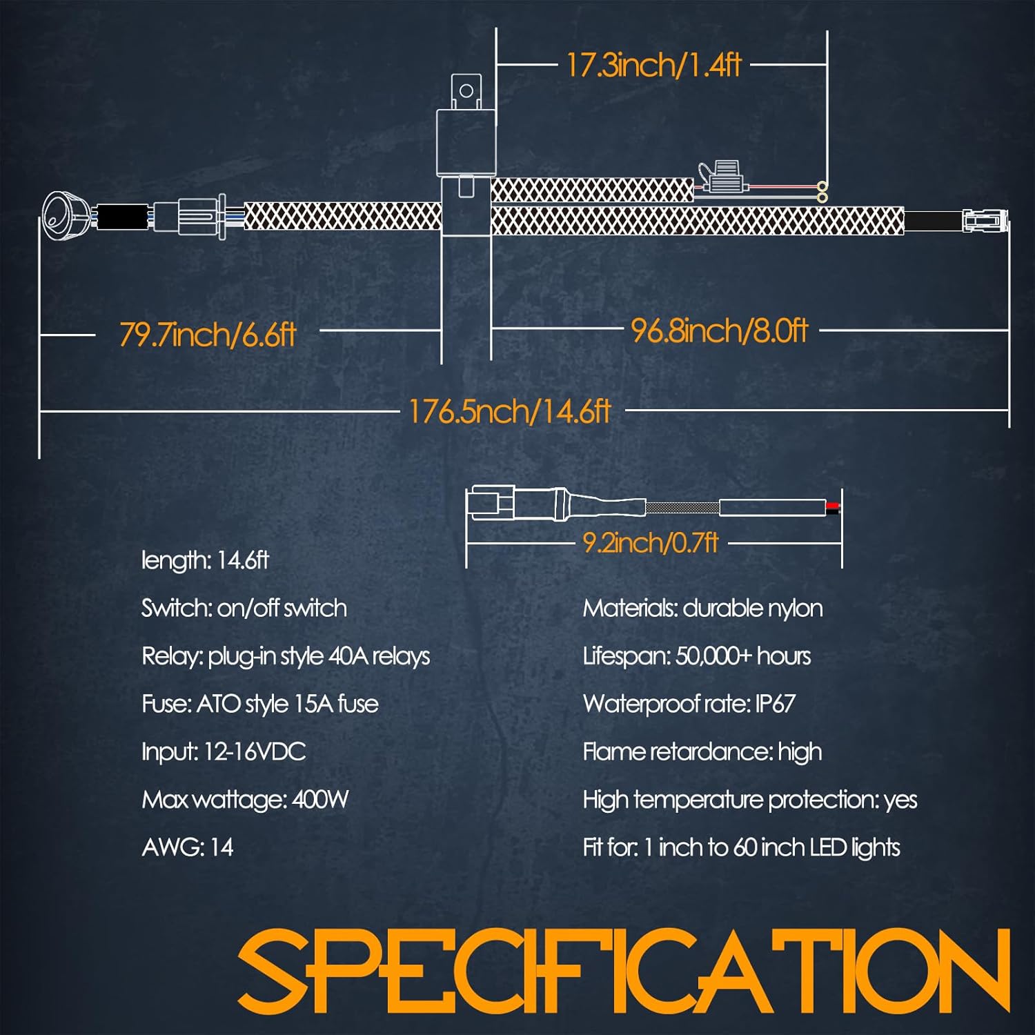
Image: Diagram illustrating the dimensions and key specifications of the wiring harness kit.
Setup and Installation
This wiring harness is designed for straightforward installation. Always ensure the vehicle's power is disconnected before beginning any electrical work.
- Connect to Power Source: Connect the red wire (positive) to the positive terminal of your 12V battery and the black wire (negative) to the negative terminal or a suitable ground point on the vehicle chassis. The harness includes ring terminals for this purpose.

Image: Close-up of the battery connection wires (red and black) with ring terminals.
- Mount the Relay: Secure the 40A plug-in style relay in a dry, accessible location away from excessive heat or moisture.
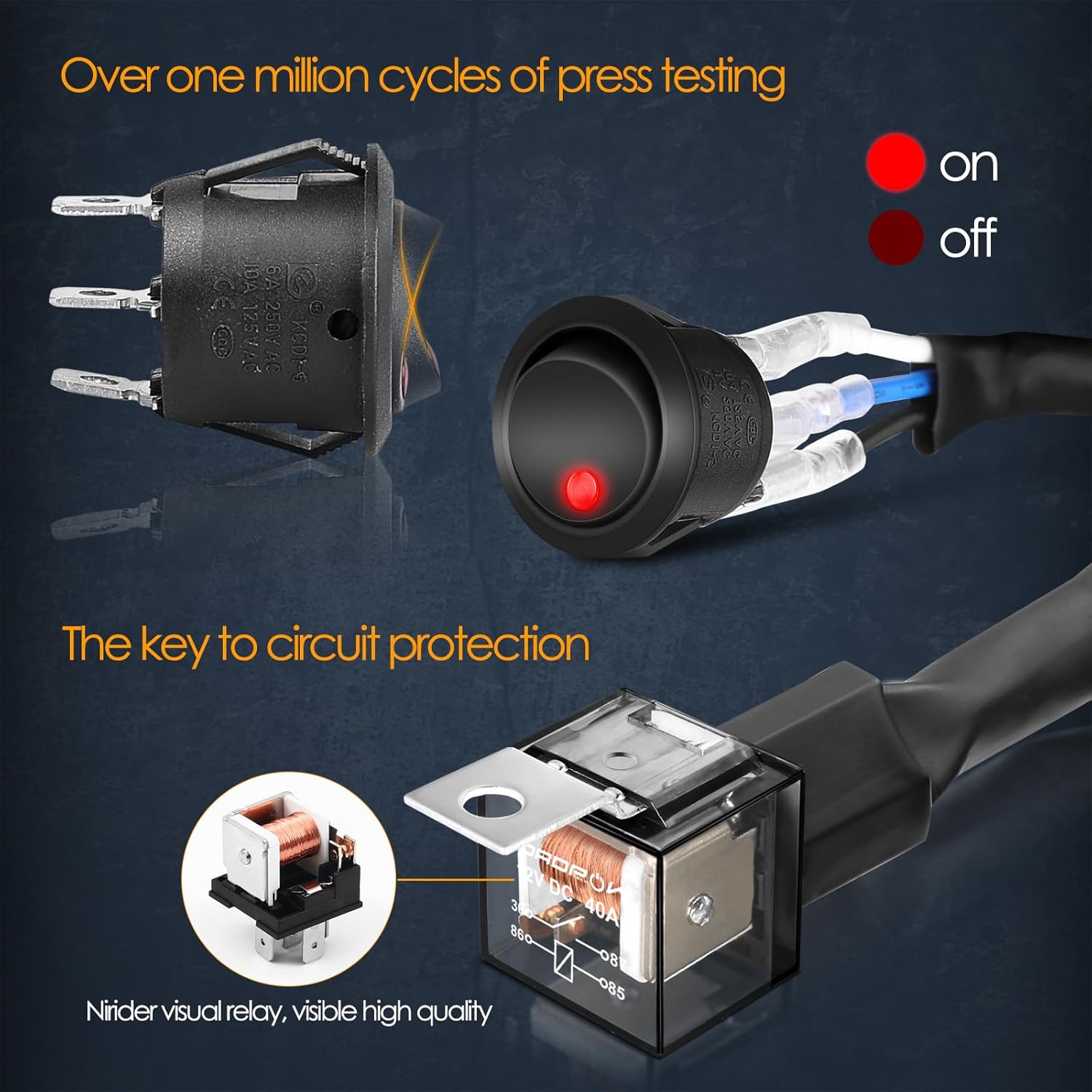
Image: Detailed view of the 40A relay and the rocker switch, highlighting their robust construction.
- Install the Rocker Switch: Choose a convenient location inside the vehicle for the red indicator light rocker switch. Drill an appropriately sized hole and secure the switch. Route the switch wires through the firewall if necessary.

Image: Close-up of the red indicator rocker switch, showing its design and connection points.
- Connect the LED Light:
- For lights with DT connectors: Directly plug the light's DT connector into the harness's DT connector.
- For bare wire lights: Use the provided DT connector adaptor. Connect the bare wires of your light to the adaptor, ensuring correct polarity (red to positive, black to negative), then plug the adaptor into the harness's DT connector.

Image: Diagram showing how to connect the harness to lights with existing DT connectors or to bare wire lights using the included adaptor.

Image: A comprehensive wiring diagram illustrating the connections for both direct plug-n-play and adaptor use.
- Secure Wiring: Route all wiring safely, away from moving parts, sharp edges, and heat sources. Use zip ties or cable clamps to secure the harness.
Operating Instructions
Once installed, operating the connected auxiliary lights is simple:
- Ensure the vehicle's ignition is in the "ON" or "ACC" position if the harness is wired to an accessory power source.
- Press the rocker switch to the "ON" position (indicated by the illuminated red light) to activate the connected auxiliary lights.
- Press the rocker switch to the "OFF" position to deactivate the lights.
Maintenance
To ensure long-lasting performance and safety of your wiring harness:
- Regular Inspection: Periodically check all connections for tightness and corrosion. Ensure wires are not frayed or damaged.
- Fuse Check: If the connected lights stop working, check the 15A ATO fuses. Replace with a fuse of the same rating if blown.
- Cleanliness: Keep connectors and the relay free from dirt and debris. The waterproof DT connectors and fuse cap help protect against moisture.
- Wire Protection: Ensure the nylon jacketed wires are not exposed to excessive friction or sharp objects that could compromise their integrity.
Troubleshooting
| Problem | Possible Cause | Solution |
|---|---|---|
| Lights do not turn on. | Blown fuse, loose power connection, faulty switch, incorrect wiring polarity. | Check and replace fuses. Verify battery and ground connections. Test switch functionality. Ensure correct positive/negative wiring. |
| Lights flicker or are dim. | Poor connection, insufficient power, damaged wiring. | Inspect all connections for corrosion or looseness. Ensure battery is adequately charged. Check wiring for damage. |
| Switch indicator light does not illuminate. | No power to the switch, faulty switch. | Verify power supply to the switch. Test or replace the switch. |
Warranty and Support
The NR NIRIDER 1 Lead DT Wiring Harness Kit comes with a 12-month quality assurance. For any issues or support, please contact Nirider customer service. They aim to respond quickly within 24 hours.
For further assistance, please refer to the manufacturer's official website or contact their support channels.