
1. Introduction
This manual provides essential information for the safe and effective operation, maintenance, and troubleshooting of your Ingco CDLI200515 20V 45Nm Torque Cordless Drill. Please read these instructions carefully before using the tool and retain them for future reference. Proper use and maintenance will ensure optimal performance and extend the life of your drill.
Safety is paramount. Always follow all safety warnings and instructions provided.
2. Product Overview
The Ingco CDLI200515 is a powerful 20V cordless drill designed for various drilling and fastening applications. It features a robust 45Nm torque, a mechanical 2-speed gear, and 15+1 torque settings for versatile use. An integrated LED work light illuminates the work area, and a spindle lock facilitates easy bit changes.
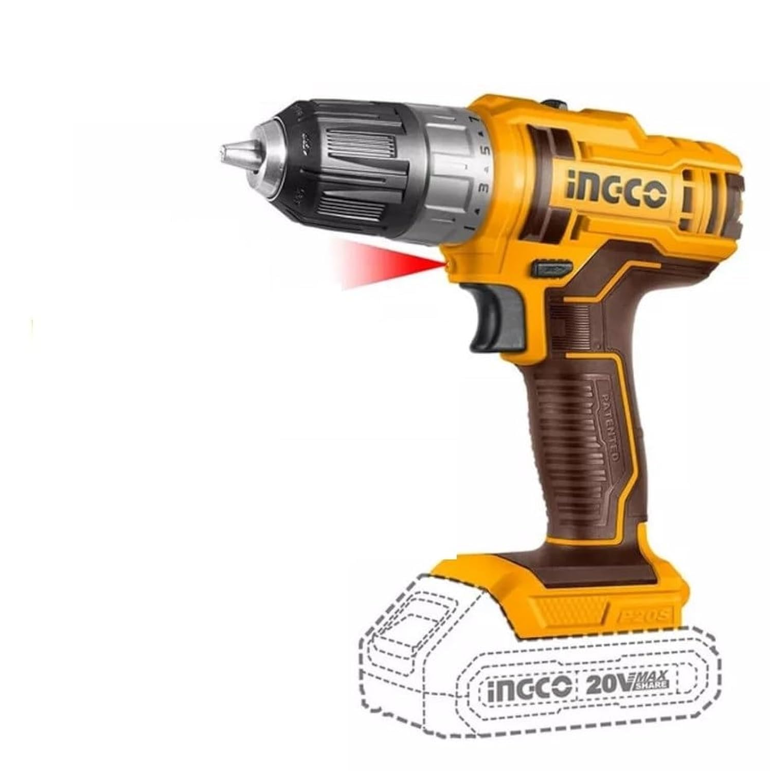
Figure 2.1: Ingco CDLI200515 Cordless Drill. Note: Battery and charger are sold separately.
Key Features:
- Powerful 20V cordless drill with 45Nm torque for tough tasks.
- 2-Speed mechanical gear for precise control and flexibility.
- 15+1 torque settings suitable for multiple applications.
- Integrated LED work light and battery power indicator.
- Lightweight design with spindle lock for easy bit changes.

Figure 2.2: Detailed view of the Ingco CDLI200515 Cordless Drill.
3. Technical Specifications
| Specification | Value |
|---|---|
| Brand | Ingco |
| Model Number | CDLI200515 |
| Power Source | Battery Powered (20V) |
| Voltage | 20 Volts |
| Maximum Torque | 45 Newton Meters |
| Number of Speeds | 2 (Mechanical Gear) |
| Torque Settings | 15+1 |
| Special Features | Built-In LED Working Light, Cordless, Spindle Lock |
| Product Dimensions (L x W x H) | 25L x 20W x 10H centimetres |
| Material | Metal, Plastic |
| Color | Yellow/Black |
4. Assembly and Setup
4.1 Battery Installation (Battery and Charger Sold Separately)
- Ensure the drill is switched off and the forward/reverse selector is in the center (locked) position.
- Align the battery pack with the base of the drill handle.
- Slide the battery pack into the handle until it clicks securely into place.
- To remove, press the battery release button(s) and slide the battery pack out.
4.2 Charging the Battery
Refer to the separate instruction manual provided with your Ingco 20V battery and charger for detailed charging procedures. Always use the correct Ingco charger for your battery pack.
4.3 Installing Drill Bits or Screwdriver Bits
- Ensure the drill is switched off and the forward/reverse selector is in the center (locked) position.
- Rotate the chuck counter-clockwise to open the chuck jaws.
- Insert the desired drill bit or screwdriver bit into the chuck, ensuring it is seated as deeply as possible.
- Rotate the chuck clockwise to tighten the chuck jaws firmly around the bit. Hand-tighten only; do not use tools to tighten the chuck.
- Verify the bit is securely held by gently pulling on it.
5. Operation
5.1 Forward/Reverse Selector
- Push the selector to the left for forward rotation (drilling/fastening screws).
- Push the selector to the right for reverse rotation (removing screws).
- Center position locks the trigger, preventing accidental startup. Always engage the lock when not in use or when changing bits.
5.2 Variable Speed Trigger
The trigger switch controls the drill's speed. Pressing the trigger further increases the speed. This allows for precise control depending on the material and application.
5.3 2-Speed Mechanical Gear Selector
The gear selector switch, located on top of the drill, allows you to choose between two speed ranges:
- Gear 1 (Low Speed, High Torque): Ideal for driving screws, larger drilling diameters, or applications requiring maximum torque.
- Gear 2 (High Speed, Low Torque): Suitable for smaller drilling diameters and faster drilling in softer materials.
Always ensure the drill is completely stopped before changing gear settings to prevent damage to the gearbox.
5.4 Torque Adjustment Ring (15+1 Settings)
The torque adjustment ring, located behind the chuck, allows you to set the desired torque for driving screws. The numbers 1-15 represent increasing torque. The drill will stop rotating once the set torque is reached, preventing overtightening or stripping screw heads.
- Settings 1-15: For driving screws. Start with a lower setting and increase as needed.
- Drill Symbol Setting: For drilling applications, this setting bypasses the clutch and provides maximum torque.
5.5 LED Work Light
The integrated LED work light automatically illuminates when the trigger is pressed, providing visibility in dimly lit work areas. It turns off shortly after the trigger is released.
6. Maintenance
6.1 Cleaning
- Always disconnect the battery pack before cleaning.
- Keep the ventilation openings of the tool clean to prevent overheating.
- Use a soft, damp cloth to clean the exterior of the drill. Do not use harsh chemicals or abrasive cleaners.
- Never immerse the tool in water or any other liquid.
6.2 Storage
- Store the drill and battery pack in a cool, dry place, away from direct sunlight and moisture.
- Ensure the battery is partially charged (around 50%) before long-term storage.
- Store out of reach of children.
7. Troubleshooting
| Problem | Possible Cause | Solution |
|---|---|---|
| Drill does not start | Battery not inserted correctly Battery discharged Forward/reverse selector in center (locked) position | Re-insert battery securely Charge battery Move selector to forward or reverse position |
| Loss of power during operation | Battery low Overload protection activated | Charge battery Reduce pressure on the tool; allow it to cool down |
| Bit slips in chuck | Chuck not tightened sufficiently Bit shank is dirty or damaged | Re-tighten chuck firmly Clean or replace bit |
| Drill stops when driving screws | Torque setting too low | Increase torque setting on the adjustment ring |
If you encounter problems not listed here or if solutions do not resolve the issue, please contact Ingco customer support.
8. Warranty and Support
Ingco products are manufactured to high-quality standards. For information regarding warranty coverage, terms, and conditions, please refer to the warranty card included with your purchase or visit the official Ingco website. For technical support, spare parts, or service inquiries, please contact your local Ingco dealer or customer service center.


