
GCSOAR TD41020F-100A
GCSOAR MPPT Solar Charge Controller User Manual
Model: TD41020F-100A
Product Overview
The GCSOAR MPPT Solar Charge Controller is designed for efficient and safe management of solar power systems. It automatically detects 12V, 24V, or 48V DC system voltages and is compatible with various battery types including Sealed Lead Acid, GEL, Flooded, LiFePO4, and Li(NiCoMn)O2 Lithium batteries. This controller features advanced MPPT technology for high tracking efficiency, real-time monitoring via a WiFi adapter and mobile application, and comprehensive safety protections.

Figure 1: GCSOAR MPPT Solar Charge Controller (100A model) with included WiFi adapter and a smartphone displaying the monitoring application.
Key Features
- Automatic Voltage Detection: Auto-detects 12V, 24V, or 48V DC system voltage.
- Multi-Battery Compatibility: Supports Sealed Lead Acid, GEL, Flooded, LiFePO4, and Li(NiCoMn)O2 Lithium batteries, with user-customizable parameters.
- High PV Input: Max PV 200V, supporting solar panel input power up to 1300W (12V), 2600W (24V), or 5200W (48V).
- Real-Time APP Monitoring: Monitor consumption and customize parameters via the iConnect App using the included WiFi adapter (CM-W01).
- Advanced Charging: Features 4-stage charging (Bulk, Absorption, Float, Equalization) for Lead Acid and 2-stage (Bulk, Absorption) for Lithium batteries, including Lithium Reactivation.
- Comprehensive Safety Protections: Includes protection against reverse polarity, battery overcharging/over-discharging, overload, short-circuiting, overheating, and reverse current. CE, FCC, IEC, UL, and RoHS certified.
- High MPPT Efficiency: Up to 99% tracking efficiency and 98% peak conversion efficiency. Capable of activating over-discharged batteries.
- User-Friendly Interface: LCD screen displays system information, customizable parameters, and error codes. Easy to mount design.
Package Contents
Upon opening the package, verify that all components are present:
- GCSOAR MPPT Solar Charge Controller (TD41020F-100A)
- User's Manual
- Temperature Line
- WiFi Adapter (CM-W01)
Video 1: GCSOAR MPPT Solar Charge Controller 100A 12V 24V 48V Unboxing. This video demonstrates the unboxing process and shows the contents of the package, including the controller, user manual, temperature line, and WiFi adapter.
Setup and Installation
Proper installation is crucial for the safe and efficient operation of your solar charge controller. Please follow these steps carefully.
1. Mounting the Controller
The controller should be mounted in a well-ventilated area, away from direct sunlight and moisture. Ensure there is sufficient space around the unit for proper heat dissipation, especially for the cooling fan.

Figure 2: Controller dimensions and cooling fan location. The image shows the physical dimensions of the controller and highlights the fan cooling system and terminal connections for PV input, battery, and temperature sensor.
2. Wiring Connections
Always connect the battery first, then the solar panel, and finally the load. Disconnect in the reverse order. Ensure all connections are secure and correct polarity is observed.
- Connect Battery: Connect the battery cables to the battery terminals on the controller. Ensure correct polarity (+ to + and - to -). The controller will power on once the battery is connected.
- Connect Solar Panel: Connect the solar panel cables to the PV input terminals on the controller. Ensure correct polarity. The controller will begin charging the battery.
- Connect Load (Optional): If using the DC load output, connect your DC appliances to the load terminals.
- Connect Temperature Sensor: Connect the included temperature line to the designated temperature sensor port. This ensures accurate battery charging based on ambient temperature.
- Connect WiFi Adapter: Plug the CM-W01 WiFi adapter into the RS485 communication port.

Figure 3: System wiring diagram. This diagram illustrates the correct connection sequence for the battery, PV panel, inverter, AC load, and the WiFi adapter to the solar charge controller.
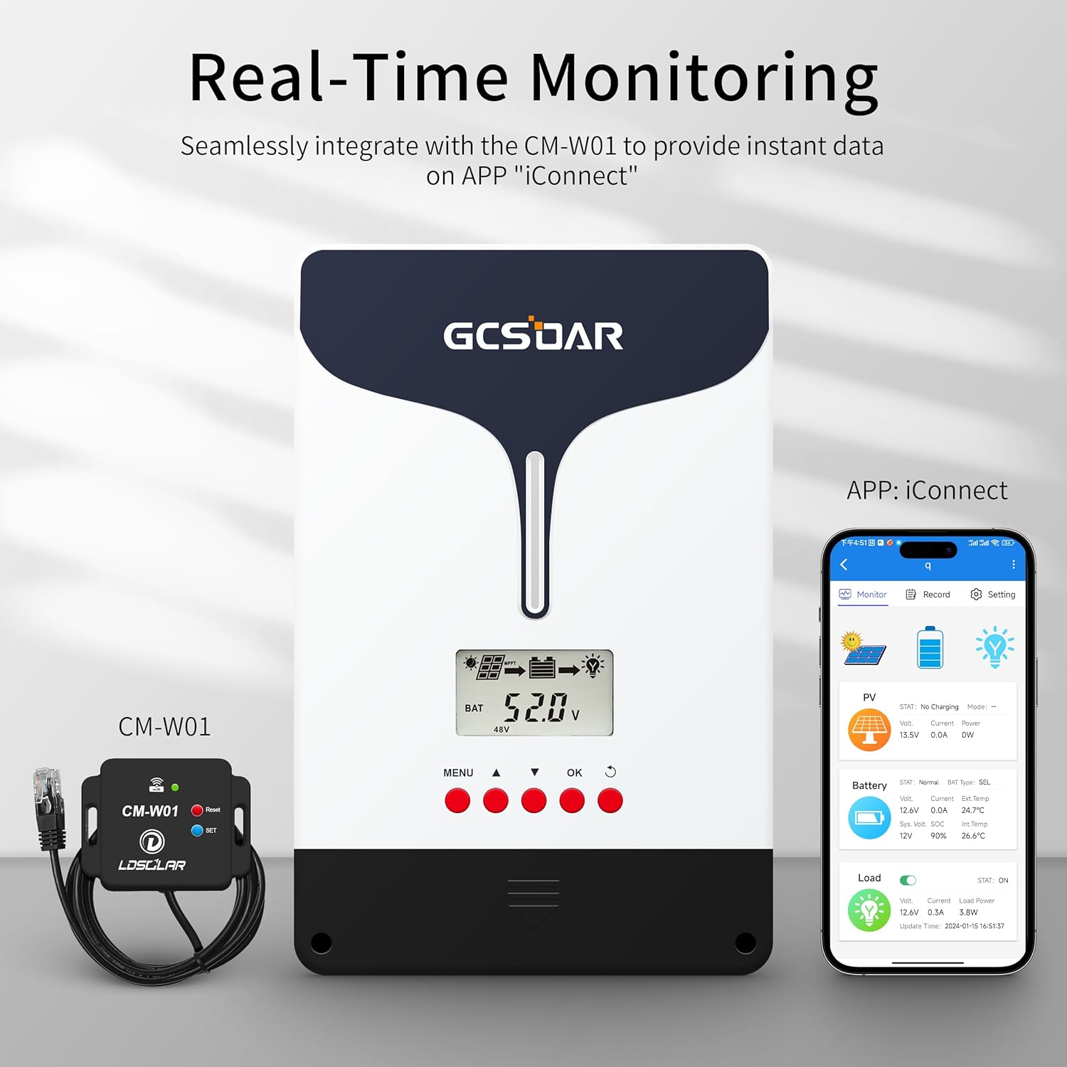
Figure 4: Real-time monitoring setup. This image shows the controller, the CM-W01 WiFi adapter, and a smartphone displaying the iConnect app, emphasizing the real-time data monitoring capability.
Operating Instructions
LCD Display and Button Functions
The controller features an LCD screen and five buttons for operation and parameter viewing.
- MENU: Press to enter the menu interface from the main display.
- ▲ (Up): Navigate up through menu options or increase parameter values.
- ▼ (Down): Navigate down through menu options or decrease parameter values.
- OK: Confirm selection or enter a setting.
- ↻ (Return/Exit): Exit from any interface or return to the previous screen.
Viewing Parameters
From the main interface (cycle display), press the "MENU" button to enter the menu. Use the Up/Down arrows to cycle through various parameters such as battery voltage, PV voltage, charge current, battery type, controller temperature, load mode, load disconnect voltage, and load reconnect voltage.

Figure 5: LCD display cycle and parameter setting. This image shows the various parameters displayed on the LCD screen, including battery voltage, PV power, accumulated charging power, float voltage, boost voltage, load reconnect/disconnect voltage, load mode, controller temperature, and battery type. It also provides instructions for navigating the menu.
Setting Parameters (Battery Type)
To set the battery type:
- From the main interface, press and hold the "OK" button for 5 seconds.
- Then, briefly press the "OK" button again and wait for "SEL" to flash. This indicates you are in the setting status.
- Use the Up/Down arrows to select the appropriate battery type (e.g., Sealed, GEL, Flooded, LiFePO4, Li(NiCoMn)O2).
- Once the desired battery type is selected, press and hold "OK" for 5 seconds to confirm. The setting is successful.

Figure 6: APP operation for setting parameters. This image shows the iConnect app interface for adjusting system parameters, including system voltage, battery type, boost charge voltage, float charge voltage, LVD voltage, LVR voltage, and load working hours.
APP Monitoring and Control
The iConnect mobile application allows for remote monitoring and parameter adjustment via the WiFi adapter.
- Download the App: Search for "LD iConnect" in the Google Play Store (Google Play) or Apple App Store (Apple App Store). Alternatively, scan the QR code in the manual or visit the official website (LDSOLAR Website).
- Register and Login: Follow the in-app instructions to register an account and log in.
- Add Device: Choose "Cloud Device" and click "Add Device" to connect your controller.
- Configure WiFi: Follow the prompts to configure WiFi information for the controller. Ensure your mobile device is connected to power and the mobile phone is nearby.
- Monitor and Record: Once connected, you can monitor real-time solar system data and record charging/discharging data.
- Set Parameters: Use the app to select battery type, confirm system voltage, and set protection parameters for your solar system.

Figure 7: APP download options. This image provides QR codes and instructions for downloading the "LD iConnect" app from Apple App Store, Google Play, or the LDSOLAR website.

Figure 8: APP connection steps. This image illustrates the four steps to connect the controller to the iConnect app: download/register/login, choose "Cloud Device" and "Add Device", configure WiFi, and then monitor/record/set parameters.
Maintenance
Regular maintenance ensures optimal performance and longevity of your solar charge controller.
- Check Connections: Periodically inspect all wiring connections for tightness and corrosion. Loose connections can cause overheating and poor performance.
- Clean Controller: Keep the controller clean and free from dust and debris. Ensure the cooling fan and vents are not obstructed.
- Battery Inspection: Regularly check battery terminals for corrosion and ensure battery fluid levels (for flooded batteries) are adequate.
- System Performance Monitoring: Use the LCD display or the iConnect app to monitor system performance regularly. Note any unusual readings or error codes.
- Environmental Conditions: Ensure the controller is operating within its specified temperature range and is protected from extreme weather conditions.
Troubleshooting
| Problem | Possible Cause | Solution |
|---|---|---|
| Controller not powering on. | Battery not connected or low voltage. | Ensure battery is connected with correct polarity and has sufficient charge. |
| No charging from solar panel. | Solar panel not connected, incorrect polarity, or insufficient sunlight. | Check PV connections and polarity. Ensure panels are receiving adequate sunlight. |
| APP connection issues. | Incorrect WiFi settings, weak signal, or app bug. | Verify WiFi adapter connection and network settings. Ensure the app is updated. Refer to the note in product features regarding fixed APP bug. |
| Battery not fully charged. | Incorrect battery type setting or insufficient PV input. | Verify battery type setting in the controller/app. Check solar panel output. |
| Overheating. | Poor ventilation or excessive load. | Ensure proper airflow around the controller. Reduce load if necessary. |
Specifications
| Parameter | Value |
|---|---|
| System Voltage | 12V/24V/48V Auto |
| Max PV Open Circuit Voltage | 200V |
| Solar Input Power (12V) | 1300W |
| Solar Input Power (24V) | 2600W |
| Solar Input Power (48V) | 5200W |
| Charging Current Rating | 100A |
| Rated Load Current | 50A |
| Operating Temperature | -20°C to +55°C |
| Dimensions (L x W x H) | 8.26 x 4.33 x 12.44 inches (210 x 110 x 316 mm) |
| Item Weight | 8.8 pounds (4 kg) |
| Display Type | LCD |
| Charging Port Type | RS485 |
| Included Components | TD41020F-WiFi (WiFi Adapter) |
Warranty and Support
GCSOAR products come with a manufacturer's warranty. For specific warranty details and duration, please refer to the warranty card included with your product or contact GCSOAR customer support.
Customer Support
For technical assistance, troubleshooting, or any product-related inquiries, please contact GCSOAR customer support. You can find contact information on the official GCSOAR website or within the product packaging.
GCSOAR has established assistance centers in Chicago (USA), Munich (Germany), Toronto (Canada), and Melbourne (Australia) to provide free technical assistance.
Visit the GCSOAR Store on Amazon for more information.
Ask a question about this manual
Ask about setup, troubleshooting, compatibility, parts, safety, or missing instructions. Manuals+ will review the question and use this page’s manual context to help answer it.