1. Introduction
The RadioMaster ER6 is a 2.4GHz 6-channel PWM ExpressLRS receiver designed for fixed-wing aircraft. It integrates built-in receiver voltage telemetry and supports external flight battery telemetry, providing essential flight data. This manual provides detailed instructions for the proper setup, operation, and maintenance of your ER6 receiver.
2. Safety Information
- Always ensure correct polarity when connecting power to the receiver. Incorrect connections can cause permanent damage.
- Operate your RC aircraft in open areas, away from people, vehicles, and obstacles.
- Regularly inspect all wiring and connections for damage or loose contacts.
- Ensure your transmitter and receiver are properly bound before each flight.
- Keep the receiver away from moisture, extreme temperatures, and strong electromagnetic fields.
3. Product Overview
The RadioMaster ER6 receiver features a compact design with multiple ports for PWM servo connections, telemetry, and power. It operates on the ExpressLRS 2.4GHz protocol, offering reliable control and data transmission.
3.1 Receiver Components and Dimensions
The ER6 receiver is designed for minimal footprint, making it suitable for various fixed-wing aircraft installations. Its robust casing protects internal components.

3.2 Port Layout
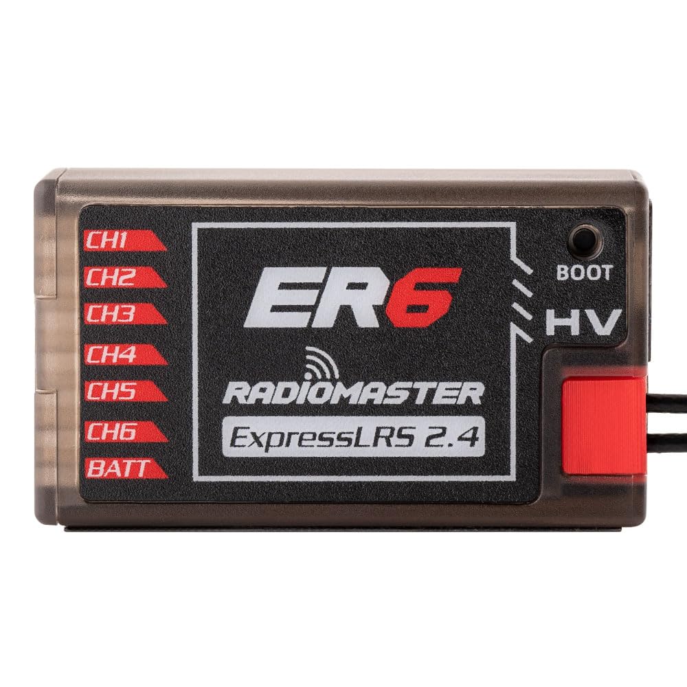
The receiver features clearly labeled ports for easy connection:
- CH1-CH6: PWM output channels for connecting servos and other PWM-controlled devices.
- BATT: Dedicated port for connecting an external flight battery for telemetry voltage sensing.
- HV: High Voltage input indicator.
- BOOT: Boot button for firmware updates.
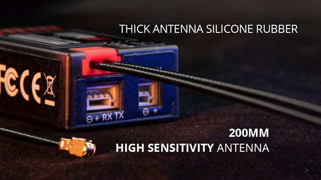
- EXT-V: External voltage input for flight battery telemetry.
- RX TX (CRSF): 4-pin CRSF input for future optional telemetry sensors.

4. Setup
4.1 Binding Procedure
To establish communication between your RadioMaster transmitter and the ER6 receiver, follow the ExpressLRS binding procedure:
- Ensure your transmitter is running ExpressLRS firmware and is configured for 2.4GHz.
- Power on the ER6 receiver. The LED on the receiver will indicate its status.
- Initiate the binding process from your transmitter's ExpressLRS Lua script or menu.
- The receiver should automatically enter binding mode if it does not detect a valid signal. Alternatively, press the BOOT button briefly while powering on the receiver to force binding mode.
- Once bound, the receiver's LED will indicate a solid connection.
4.2 Connecting Servos and Telemetry
Connect your aircraft's servos to the corresponding PWM channels (CH1-CH6) on the receiver. The ER6 supports up to 6 servos.

For external flight battery telemetry, connect the battery voltage sensor to the EXT-V port. The receiver also provides built-in voltage telemetry for its own power supply.

4.3 WiFi Updates and WebUI Configuration
The ER6 receiver supports firmware updates and configuration via WiFi and a web user interface (WebUI). This allows for convenient updates without needing to physically connect to a computer.
- Power on the receiver.
- Connect to the receiver's WiFi hotspot from your computer or mobile device. The default SSID is typically "ExpressLRS RX" and the password is "expresslrs".
- Open a web browser and navigate to the receiver's IP address (usually 10.0.0.1).
- From the WebUI, you can update firmware, configure receiver settings, and monitor status.
5. Operating
Once the receiver is properly installed and bound to your transmitter, ensure all control surfaces respond correctly to your transmitter inputs. Monitor telemetry data on your transmitter screen, including receiver voltage and external battery voltage, to ensure safe operation.
6. Maintenance
- Antenna Care: Ensure antennas are not kinked or damaged. Position them at a 90-degree angle to each other for optimal signal diversity.
- Firmware Updates: Regularly check the official ExpressLRS website for the latest firmware updates to ensure optimal performance and access to new features. Update via the WebUI as described in Section 4.3.
- Physical Inspection: Periodically inspect the receiver for any physical damage, loose connections, or debris.
7. Troubleshooting
- No Bind: Ensure both transmitter and receiver are running compatible ExpressLRS firmware. Re-attempt the binding procedure. Check power supply to the receiver.
- No Telemetry Data: Verify that the EXT-V sensor is correctly connected and that telemetry is enabled in your transmitter's ExpressLRS settings.
- Intermittent Signal/Range Issues: Check antenna placement and condition. Ensure no carbon fiber or metal parts are obstructing the antenna's line of sight to the transmitter. Avoid operating near sources of 2.4GHz interference.
- Receiver LED Status: Refer to the ExpressLRS documentation for specific LED flash codes to diagnose issues.
8. Specifications
| Model | RadioMaster ER6 |
| Frequency | 2.4GHz |
| Channels | 6 PWM |
| Input Voltage | DC 4.5-8.4V |
| Telemetry | Built-in Receiver Voltage, External Battery Voltage (EXT-V) |
| Antenna | 200mm High Sensitivity |
| Dimensions | 43mm x 25mm x 15mm |
| Firmware | ExpressLRS |
9. Warranty
RadioMaster products are typically covered by a limited manufacturer's warranty against defects in materials and workmanship. Please refer to the official RadioMaster website or your retailer for specific warranty terms and conditions, as these may vary by region and product. Keep your proof of purchase for warranty claims.
10. Support
For technical support, firmware downloads, and additional resources, please visit the official RadioMaster website or the ExpressLRS project website. You may also contact your authorized dealer for assistance.
- RadioMaster Official Website: www.radiomasterrc.com
- ExpressLRS Project: www.expresslrs.org


