
novorik XQJ001000
NOVORIK 10-inch Sliding Compound Miter Saw
Model: XQJ001000
1. Safety Instructions
WARNING: Read and understand all instructions before operating this tool. Failure to follow all instructions listed below may result in electric shock, fire, and/or serious personal injury.
- Always wear eye protection, hearing protection, and a dust mask when operating the miter saw.
- Ensure the workpiece is securely clamped before making any cuts.
- Keep hands and fingers away from the blade area. Never reach into the blade path.
- Ensure the blade guard is functioning correctly and is in place before operation.
- Disconnect the power supply before changing blades, performing maintenance, or clearing jammed material.
- Do not operate the saw in damp or wet conditions.
- Keep the work area clean and well-lit. Cluttered or dark areas invite accidents.
- Use only sharp, correctly sized blades for the material being cut.
- Never force the tool. Allow the saw to reach full speed before beginning a cut.
2. Product Overview
2.1 Components
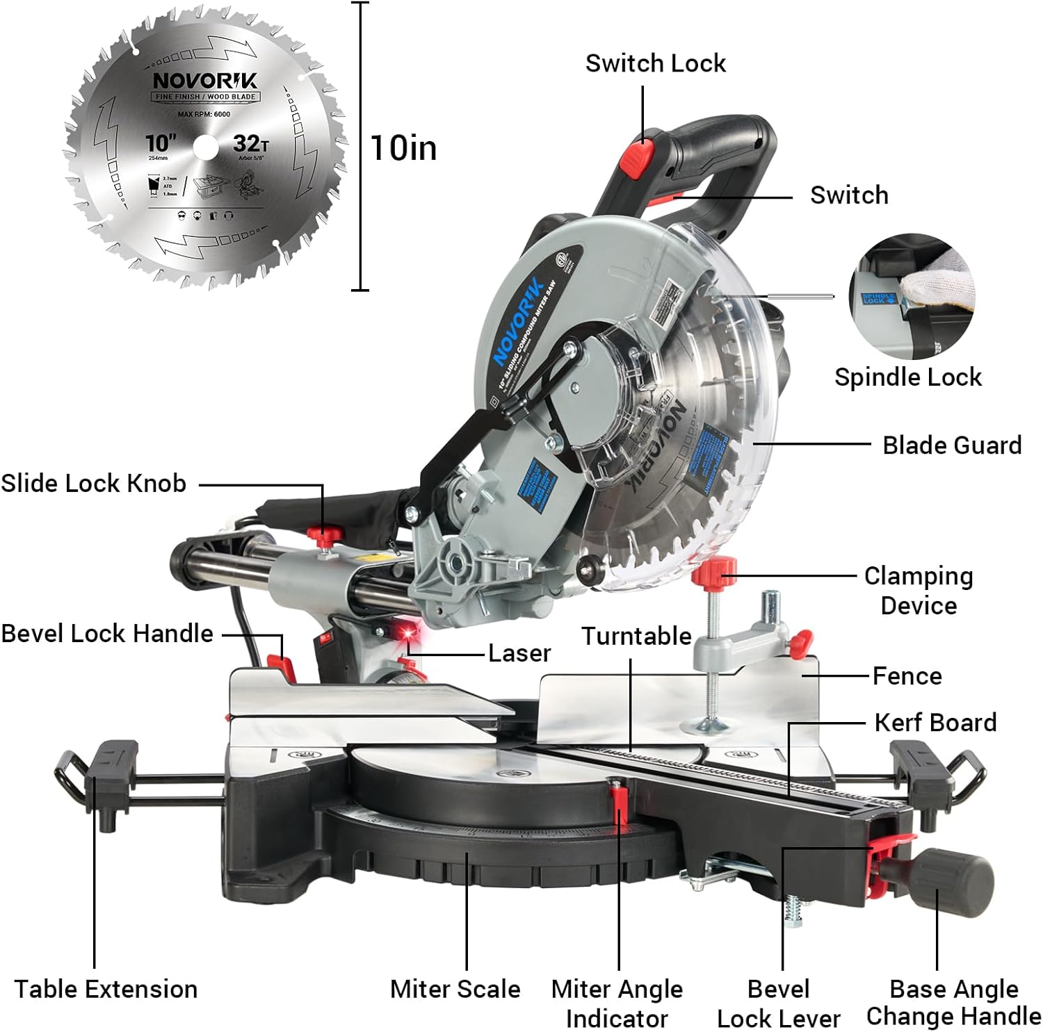
Detailed diagram identifying key components of the miter saw, including the switch, spindle lock, blade guard, laser, turntable, fence, clamping device, slide lock knob, bevel lock handle, table extension, miter scale, miter angle indicator, bevel lock lever, and base angle change handle.
- Switch: Activates and deactivates the motor.
- Switch Lock: Prevents accidental startup.
- Spindle Lock: Secures the blade for changing.
- Blade Guard: Retracts during cutting, covers blade when not in use for safety.
- Laser: Projects a guide line for precise cuts.
- Turntable: Rotates for miter angle adjustments.
- Fence: Supports the workpiece during cutting.
- Clamping Device: Secures the workpiece to the table.
- Slide Lock Knob: Locks the sliding mechanism.
- Bevel Lock Handle: Secures the saw head at desired bevel angles.
- Table Extension: Provides additional support for longer workpieces.
- Miter Scale: Indicates the miter angle setting.
- Miter Angle Indicator: Points to the current miter angle.
- Bevel Lock Lever: Releases the saw head for bevel adjustments.
- Base Angle Change Handle: Used to adjust the miter angle.
2.2 Specifications
| Specification | Value |
|---|---|
| Brand | NOVORIK |
| Model Number | XQJ001000 |
| Blade Diameter | 10 inches |
| Power Source | Corded Electric |
| Voltage | 110 Volts |
| Wattage | 1800 Watts |
| Amperage | 15 Amps |
| No-load Speed | 4,000 RPM |
| Blade Material | Tungsten Carbide |
| Number of Teeth (Included Blade) | 40T |
| Bevel Cutting Angle | 0° to 45° |
| Miter Cutting Angle | -45°/0°/+45° with positive stops |
| Special Feature | Laser Guide |
| Product Dimensions (L x W x H) | 22" x 20.4" x 38" |
| Item Weight | 22 pounds (10 kg) |
3. Setup
3.1 Unpacking and Assembly
- Carefully remove all components from the packaging. Inspect for any damage.
- Ensure all listed components are present. Refer to the parts diagram in Section 2.1.
- Mount the miter saw securely to a stable workbench using appropriate fasteners.
- Attach any included table extensions or support arms as per the manufacturer's instructions.
3.2 Blade Installation/Replacement
- Disconnect the saw from the power supply.
- Lift the lower blade guard.
- Press and hold the spindle lock button to prevent the blade from rotating.
- Using the appropriate wrench, loosen the blade bolt by turning it counter-clockwise.
- Remove the outer flange and the old blade.
- Clean the blade flanges and spindle.
- Place the new blade onto the spindle, ensuring the teeth are pointing downwards towards the front of the saw.
- Reinstall the outer flange and blade bolt. Tighten the blade bolt securely by turning it clockwise while holding the spindle lock.
- Ensure the blade guard moves freely and covers the blade when the saw is in the upright position.
4. Operation
4.1 General Cutting Procedures
- Ensure the workpiece is free of nails, screws, or other foreign objects.
- Position the workpiece firmly against the fence and table. Use the clamping device to secure it.
- Hold the saw handle firmly.
- Press the switch to start the motor and allow the blade to reach full speed.
- Slowly lower the saw head into the workpiece, applying steady, even pressure. For sliding cuts, push the saw head forward through the material.
- Once the cut is complete, release the switch and allow the blade to stop completely before raising the saw head.
4.2 Adjusting Miter Angle

A four-step visual guide detailing how to adjust the miter angle: 1. Loosen miter lock knob, 2. Pull up miter detent lever, 3. Move table to desired angle, 4. Pull down miter detent lever and lock miter lock knob.
- Loosen the miter lock knob located at the front of the saw.
- Pull up the miter detent lever to disengage the positive stops.
- Rotate the turntable to the desired miter angle, indicated on the miter scale.
- For positive stops (e.g., 0°, 15°, 22.5°, 30°, 45°), align the indicator and push down the miter detent lever.
- Tighten the miter lock knob to secure the turntable in position.
4.3 Adjusting Bevel Angle

A three-step visual guide explaining how to adjust the bevel angle: 1. Loosen the Bevel Lock Handle 1/2 turn counter-clockwise, 2. Move the blade assembly left to the desired angle, 3. Rotate the Bevel Lock Handle clockwise to secure.
- Loosen the bevel lock handle by turning it approximately 1/2 turn counter-clockwise.
- Tilt the saw head to the left to the desired bevel angle (0° to 45°), as indicated on the bevel scale.
- Rotate the bevel lock handle clockwise to securely lock the saw head in the chosen position.
4.4 Using the Laser Guide

Close-up view of the miter saw's integrated laser guide, projecting a red line onto a wooden workpiece to assist in achieving accurate and precise cuts.
The integrated laser guide projects a visible line onto your workpiece, indicating the exact cutting path of the blade. To activate the laser, locate the laser switch (refer to Section 2.1 Components). Use the laser to align your cut line on the material for enhanced precision.
4.5 Cutting Capacities

Visual representation of the maximum cutting dimensions for different types of cuts: 90° straight (cross cut), 45° miter, 45° straight bevel, and 45° compound cuts.
The saw offers various cutting capacities depending on the angle settings:
- Max Cross Cut (90° Straight): 4-1/4" x 13-5/8"
- Max Miter (45°): 4-1/4" x 9-3/4"
- Max Bevel (45° Straight): 2-1/4" x 13-3/8"
- Max Compound (45° Miter, 45° Bevel): 2-1/4" x 9-3/4"
4.6 Compatible Materials

Illustrations demonstrating the versatility of the miter saw in cutting different materials such as wood, plastic pipes, copper, and ceramic tiles, highlighting its multi-material capability.
This miter saw is designed for cutting a variety of materials, including:
- Wood
- Plastic (e.g., PVC)
- Soft Metals (e.g., Copper)
- Ceramic Tile (with appropriate blade)
Always ensure you use the correct blade type for the material being cut. The included blade is suitable for woodworking.
5. Maintenance
WARNING: Always disconnect the power cord before performing any maintenance or cleaning.
- Cleaning: Regularly clean the saw, especially the blade area, blade guard, and dust port, to prevent sawdust buildup. Use a brush or compressed air. Do not use solvents that may damage plastic parts.
- Blade Inspection: Inspect the blade before each use for sharpness, cracks, or missing teeth. Replace damaged or dull blades immediately.
- Lubrication: Periodically apply a light coat of machine oil to moving parts, such as the sliding rails, to ensure smooth operation.
- Fasteners: Check all nuts, bolts, and screws periodically to ensure they are tight. Tighten any loose fasteners.
- Carbon Brushes: The motor's carbon brushes may require periodic inspection and replacement. Refer to a qualified service technician for this procedure.
6. Troubleshooting
| Problem | Possible Cause | Solution |
|---|---|---|
| Saw does not start | No power supply Faulty switch Tripped circuit breaker | Check power connection Contact service technician Reset circuit breaker |
| Blade not cutting smoothly or burning wood | Dull or damaged blade Incorrect blade for material Feeding too fast | Replace blade Install correct blade Reduce feed rate |
| Inaccurate cuts | Loose fence or table Blade deflection Laser misalignment | Tighten all fasteners Replace blade Adjust laser (refer to service manual or technician) |
| Excessive vibration | Loose blade Damaged blade Unstable mounting | Tighten blade bolt Replace blade Securely mount saw to workbench |
7. Warranty and Support
For warranty information, technical support, or service inquiries, please refer to the warranty card included with your product or contact NOVORIK customer service directly. Keep your purchase receipt as proof of purchase.
Contact information for support can typically be found on the manufacturer's official website or on the product packaging.
Ask a question about this manual
Ask about setup, troubleshooting, compatibility, parts, safety, or missing instructions. Manuals+ will review the question and use this page’s manual context to help answer it.