1. Introduction
This instruction manual provides essential information for the safe and effective operation of your PEAKMETER PM2128 / PM2128S Digital Clamp Multimeter. Please read this manual thoroughly before use and retain it for future reference. This device is designed for measuring AC/DC voltage, AC/DC current, resistance, capacitance, frequency, temperature, and performing continuity tests.
1.1 Safety Information
Always adhere to basic safety precautions when using this instrument to avoid potential electric shock, injury, or damage to the meter or equipment under test. Pay close attention to all warnings and cautions.
- Do not apply voltage or current that exceeds the maximum specified limits.
- Exercise extreme caution when working with live circuits.
- Ensure the test leads are in good condition and properly connected.
- Do not operate the meter if it appears damaged or if the case is open.
- Always turn off power to the circuit and discharge all high-voltage capacitors before measuring resistance, continuity, or capacitance.
- Replace batteries when the low battery indicator appears to ensure accurate readings.
2. Product Overview
The PEAKMETER PM2128 / PM2128S is a compact and versatile digital clamp multimeter featuring auto-ranging capabilities and a 6000-count display. It is designed for precise electrical measurements in various applications.

Figure 2.1: PEAKMETER PM2128 Digital Clamp Multimeter with its packaging and carrying case.
2.1 Key Features
- Auto and Manual Ranging: Automatically selects the appropriate measurement range, with an option for manual selection.
- 6000 Counts Display: Provides high-resolution readings.
- True RMS: Accurate measurements for non-sinusoidal waveforms (PM2128S model).
- Overload Protection: Ensures safety across all measurement ranges.
- Automatic Shutdown: Conserves battery life by powering off after 10 minutes of inactivity.
- Max Voltage: Capable of handling up to 1000V DC or 1000V AC between measurement terminal and ground.
- Diverse Measurements: Includes DC/AC Voltage, AC/DC Current, Resistance, Capacitance, Frequency, Temperature, LowZ, and DC uA.
- Non-Contact Voltage (NCV): Detects AC voltage without direct contact.
- Analogue Bar Graph Display: Provides a visual representation of measurement trends.

Figure 2.2: Visual representation of the multimeter's fully functional capabilities.
2.2 Components
Familiarize yourself with the main components of the clamp multimeter:
- Clamp Jaw: Used for non-contact AC/DC current measurement.
- Rotary Switch: Selects the primary measurement function.
- LCD Display: Shows measurement readings, units, and indicators.
- Function Buttons: (e.g., FUNC, RAN, REL, HOLD, HZ/%) For selecting sub-functions, range, relative measurement, data hold, and frequency/duty cycle.
- Input Jacks: For connecting test leads (COM, INPUT).
- Trigger: Opens the clamp jaw.
- NCV Sensor: Located at the top of the clamp jaw for non-contact voltage detection.
- Flashlight: Provides illumination in dark environments.

Figure 2.3: Detailed view of the NCV sensor and flashlight on the clamp meter.
3. Setup
3.1 Battery Installation
The PEAKMETER PM2128 / PM2128S requires 1 Lithium Polymer battery (included). To install or replace the battery:
- Ensure the meter is turned OFF.
- Locate the battery compartment cover on the back of the meter.
- Use a screwdriver to loosen the screw securing the cover.
- Remove the cover and insert the battery, observing correct polarity (+ and -).
- Replace the battery cover and tighten the screw.
3.2 Power On/Off
To power on the meter, rotate the rotary switch from the 'OFF' position to any desired measurement function. To power off, rotate the rotary switch back to the 'OFF' position. The meter also features an automatic shutdown function after approximately 10 minutes of inactivity to conserve battery life.
4. Operating Instructions
This section details how to perform various measurements using your clamp multimeter.
4.1 AC/DC Voltage Measurement
- Insert the black test lead into the 'COM' jack and the red test lead into the 'INPUT' jack.
- Rotate the rotary switch to the 'V~' (AC Voltage) or 'V=' (DC Voltage) position. If the symbol is combined, press the 'FUNC' button to toggle between AC and DC.
- Connect the test leads in parallel to the circuit or component you wish to measure.
- Read the voltage value on the LCD display.
4.2 AC/DC Current Measurement (Clamp)
Caution: For current measurement using the clamp, ensure only one conductor passes through the clamp jaw. Measuring multiple conductors will result in an inaccurate reading.

Figure 4.1: Operating the clamp jaw for current measurement.
- Rotate the rotary switch to the 'A~' (AC Current) or 'A=' (DC Current) position. If the symbol is combined, press the 'FUNC' button to toggle between AC and DC.
- Press the trigger to open the clamp jaw.
- Enclose a single conductor of the circuit with the clamp jaw.
- Release the trigger to close the clamp jaw around the conductor.
- Read the current value on the LCD display.
4.3 Resistance Measurement
- Insert the black test lead into the 'COM' jack and the red test lead into the 'INPUT' jack.
- Rotate the rotary switch to the 'Ω' (Resistance) position.
- Ensure the circuit is de-energized and all capacitors are discharged.
- Connect the test leads across the component to measure its resistance.
- Read the resistance value on the LCD display.
4.4 Capacitance Measurement
- Insert the black test lead into the 'COM' jack and the red test lead into the 'INPUT' jack.
- Rotate the rotary switch to the 'F' (Capacitance) position.
- Ensure the capacitor is fully discharged before connecting the test leads.
- Connect the test leads across the capacitor terminals.
- Read the capacitance value on the LCD display.
4.5 Frequency Measurement
- Insert the black test lead into the 'COM' jack and the red test lead into the 'INPUT' jack.
- Rotate the rotary switch to the 'Hz' (Frequency) position.
- Connect the test leads in parallel to the circuit where you want to measure frequency.
- Read the frequency value on the LCD display.
4.6 Temperature Measurement
If your model includes a K-type thermocouple (check package contents), you can measure temperature:
- Rotate the rotary switch to the 'TEMP' position.
- Insert the K-type thermocouple into the input jacks, observing polarity.
- Place the thermocouple probe on or near the object whose temperature you wish to measure.
- Read the temperature value on the LCD display.
4.7 Continuity Test
- Insert the black test lead into the 'COM' jack and the red test lead into the 'INPUT' jack.
- Rotate the rotary switch to the continuity symbol (often shared with resistance or diode test, use 'FUNC' to select).
- Ensure the circuit is de-energized.
- Connect the test leads across the component or wire.
- If the resistance is below approximately 30Ω, the buzzer will sound, indicating continuity.
4.8 Non-Contact Voltage (NCV) Detection
- Rotate the rotary switch to the 'NCV' position.
- Move the top of the clamp jaw (where the NCV sensor is located) close to the conductor or outlet.
- The meter will indicate the presence of AC voltage through audible beeps and/or visual indicators on the display.
4.9 Low Impedance Voltage (LowZ) Measurement
The LowZ function is designed to detect ghost voltages by providing a low impedance input. This helps to drain away stray voltages that can give false readings on standard high-impedance multimeters.
- Insert the black test lead into the 'COM' jack and the red test lead into the 'INPUT' jack.
- Rotate the rotary switch to the 'LowZ' position.
- Connect the test leads in parallel to the circuit.
- Read the voltage value on the LCD display.
4.10 Data Hold Function
Press the 'HOLD' button to freeze the current reading on the display. Press it again to release the hold and resume live measurements.
5. Specifications
The following table outlines the technical specifications for the PEAKMETER PM2128 and PM2128S models.

Figure 5.1: Comprehensive specifications for PM2128 and PM2128S.
| Feature | Specification |
|---|---|
| Model Number | EC-PM2128 |
| Display | 6000 Counts |
| Power Source | 1 Lithium Polymer battery (included) |
| Automatic Shutdown Time | 10 minutes |
| Max Voltage (Input to Ground) | 1000V DC or 1000V AC |
| Product Dimensions (L x W x H) | 5.91 x 3.94 x 7.09 inches (150 x 100 x 180 mm) |
| Item Weight | 1 Kilogram (approx. 2.2 Pounds) |
| Safety Rating | EN61010-1, EN61010-2-032, EN61326, CAT.III 1000V |
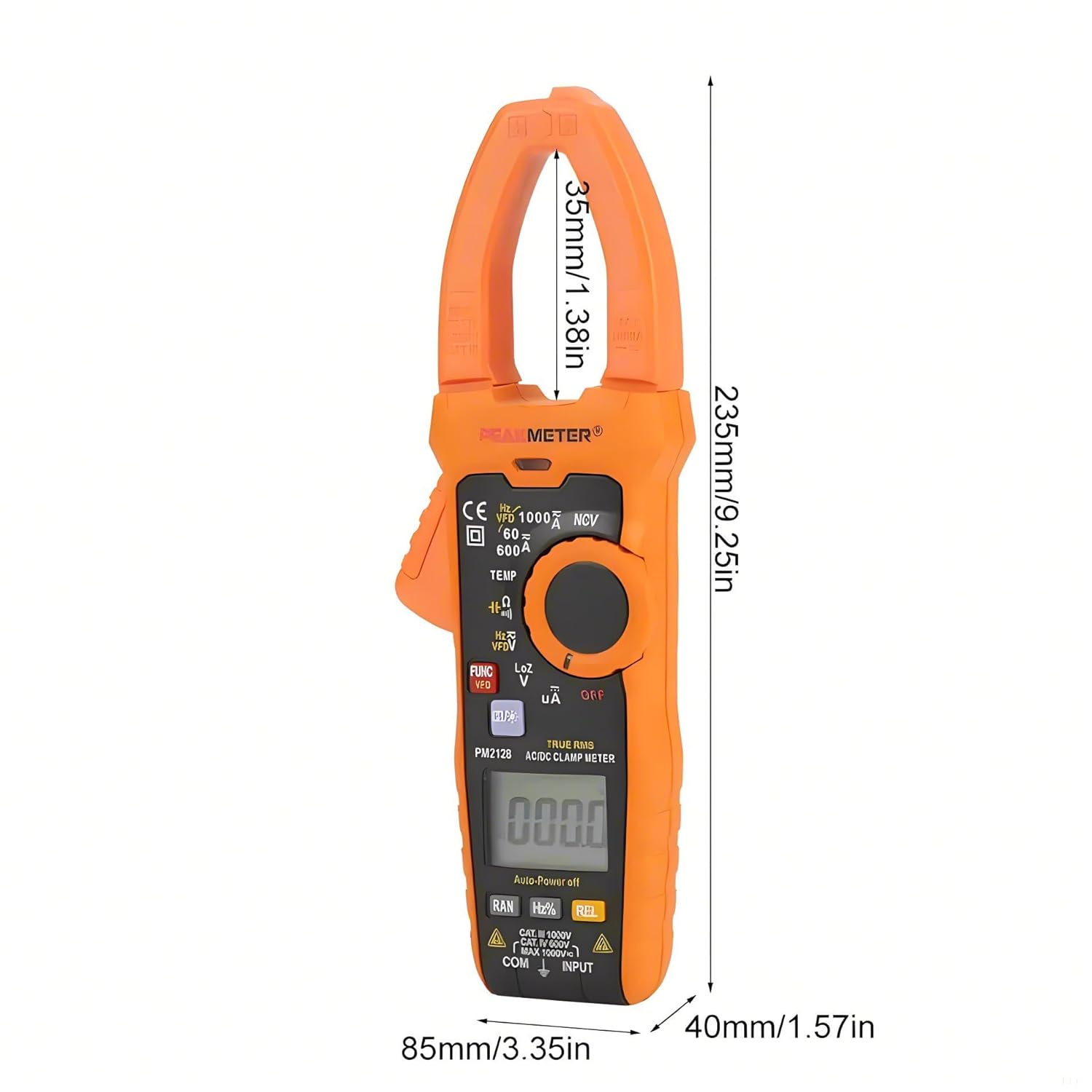
Figure 5.2: Dimensions of the PEAKMETER PM2128.
6. Maintenance
6.1 Cleaning
To clean the meter, wipe the case with a damp cloth and a mild detergent. Do not use abrasives or solvents. Ensure the meter is completely dry before use.
6.2 Battery Replacement
When the low battery indicator appears on the display, replace the battery promptly to ensure accurate measurements. Refer to Section 3.1 for battery installation instructions.
6.3 Storage
If the meter is not used for an extended period, remove the battery to prevent leakage and damage. Store the meter in a cool, dry place, away from direct sunlight and extreme temperatures.
7. Troubleshooting
This section addresses common issues you might encounter with your clamp multimeter.
- No Display: Check if the rotary switch is in an 'OFF' position. Ensure the battery is correctly installed and has sufficient charge. Replace the battery if necessary.
- Inaccurate Readings: Verify that the correct measurement function is selected. Check test lead connections and ensure they are not damaged. Ensure the battery is not low. For current measurements, confirm only one conductor is within the clamp jaw.
- Meter Shuts Off Automatically: This is a normal function (Auto Power Off) after 10 minutes of inactivity. To disable or reset, refer to the specific instructions in the full product manual if available, or simply turn the rotary switch to 'OFF' and then back to the desired function.
- 'OL' or 'OVER' on Display: Indicates an overload or out-of-range measurement. Select a higher range if available, or ensure the input does not exceed the meter's maximum specifications.
8. Warranty and Support
PEAKMETER products are manufactured to high-quality standards. This product is covered by a standard manufacturer's warranty against defects in materials and workmanship. For specific warranty terms, duration, and to obtain technical support or service, please refer to the warranty card included with your product or contact your point of purchase. Please have your model number (PM2128 or PM2128S) and purchase information ready when contacting support.


