1. Introduction
The SEQURE M10-25Q GPS Module is designed for FPV racing drones and fixed-wing UAVs. It features a 10th generation UBLOX chip, supporting dual NMEA and UBX protocols, and integrates a QMC5883L compass for accurate positioning. This module offers fast satellite acquisition and stable signal reception, suitable for various drone applications.
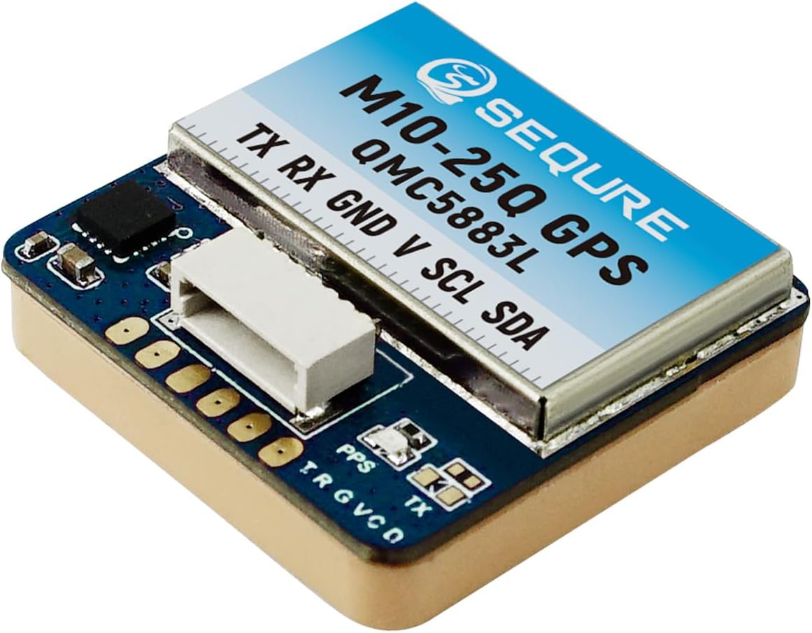
Image 1: SEQURE M10-25Q FPV GPS Module. This image shows the compact design of the GPS module with its integrated QMC5883L compass and connection pins.
2. Key Features
- Advanced Chipset: Utilizes a 10th generation UBLOX chip for rapid and precise positioning.
- Dual Protocol Support: Compatible with both UBLOX and NMEA output protocols.
- Integrated Compass: Features a QMC5883L compass for accurate directional data.
- Multi-Constellation Support: Supports GPS, GLONASS, BDS, GALILEO, SBAS, and QZSS satellite systems.
- High Output Frequency: Provides up to 10Hz output frequency for real-time data.
- Compact Design: Small and lightweight (25x25x8mm, 12.2g) for easy integration into various drone sizes.
- Stable Signal Reception: Equipped with a high-quality ceramic antenna for effective satellite signal acquisition.
- Flexible Connection: Offers both direct plug-in (SH1.0-6P connector) and soldering pad options.

Image 2: Overview of SEQURE M10-25Q GPS Module features. This graphic highlights key attributes such as stable signal, fast positioning, compact size, plug-in connection, strong compatibility, and integrated QMC5883L compass.

Image 3: Illustration of the U-blox M10 10th Generation Chip. This image emphasizes the advanced chipset integrated with the QMC5883L compass for accurate position identification.
3. Specifications

Image 4: Detailed specifications table for SEQURE M10-12, M10-18, and M10-25Q GPS modules. This table provides a comparative overview of technical parameters for different models in the series.
| Parameter | Value |
|---|---|
| Model | M10-25Q GPS |
| Chip | M10 |
| Frequency | GPS L1, GLONASS L1, BDS B1, GALILEO E1, SBAS L1, QZSS L1 |
| Power Supply | 5V |
| Size | 25 x 25 x 8 mm |
| Weight | 12.2 g |
| Interface | SH1.0-6P connector, PCB pad |
| Antenna | Ceramic Antenna |
| Receiving Channels | 72 search channels |
| Baud Rate | 115200 |
| Output Protocol | NMEA, UBX dual protocol, I2C (Mag) |
| Compass | QMC5883L |
| Output Frequency | 1Hz-10Hz, default 10Hz |
| Speed Accuracy | 0.05 m/s |
| Horizontal Positioning Accuracy | 2D ACC 1.5m (Outdoor) |
| Receive Sensitivity | Trace -162dBm, Capture -160dBm |
| Working Temperature | -40℃ ~ +85℃ |
| Storage Temperature | -40℃ ~ +105℃ |
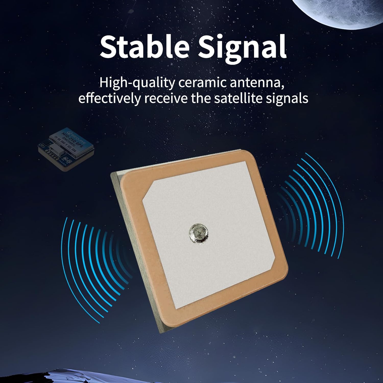
Image 5: Illustration of the stable signal reception provided by the high-quality ceramic antenna of the SEQURE M10-25Q GPS module.

Image 6: Comparison illustrating that a larger antenna area generally leads to faster satellite search speed. The M10-25Q has the largest antenna area among the M10 series.

Image 7: Size and weight comparison of SEQURE M10-12, M10-18, and M10-25Q GPS modules. This image provides visual context for the physical dimensions of each model.
4. Setup and Installation
The M10-25Q GPS module offers two primary connection methods: direct plug-in using the SH1.0-6P connector or soldering to PCB pads. It is recommended for use with INAV firmware.
4.1 Wiring Diagram
Important: Ensure correct wiring before applying power to prevent potential damage to the product or connected components.
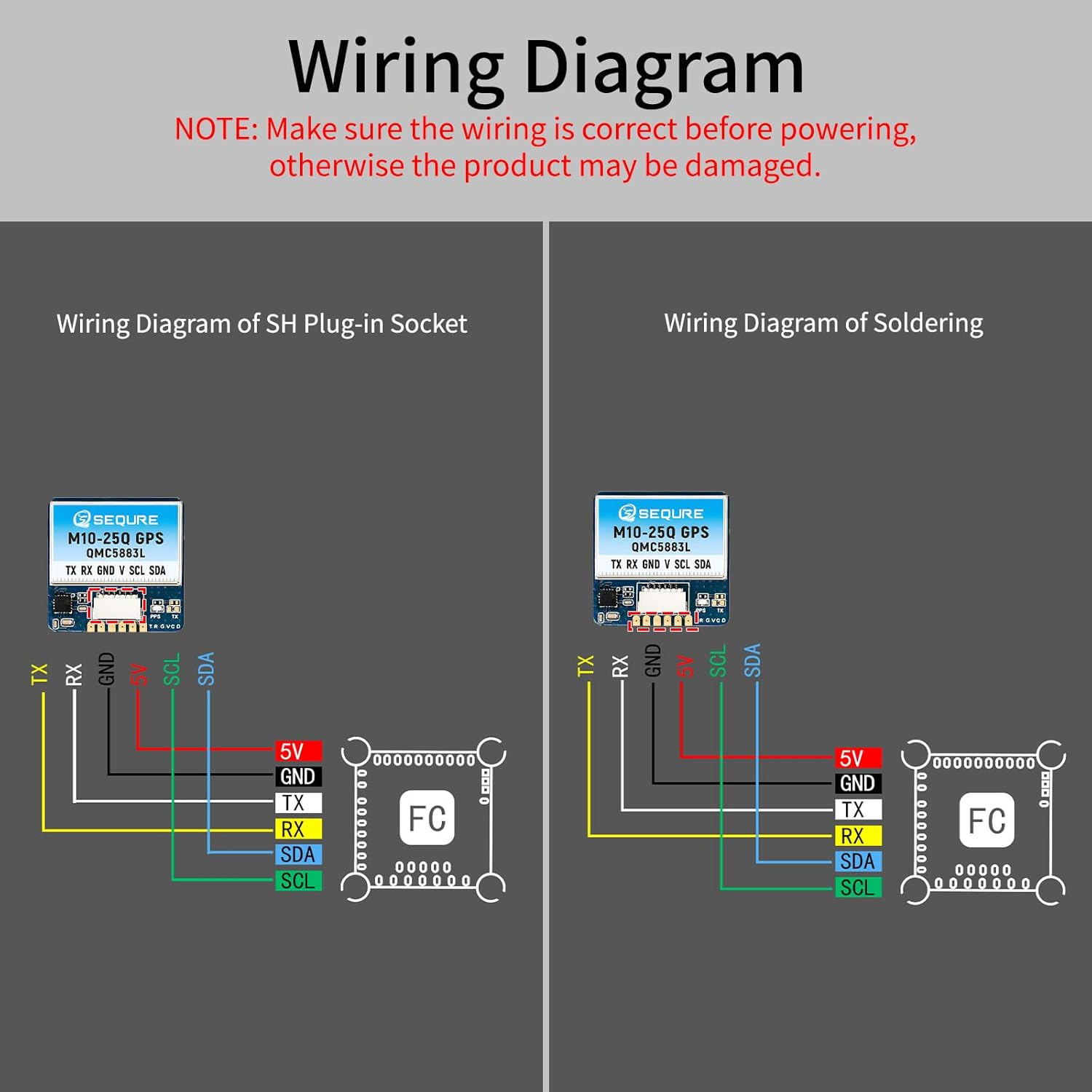
Image 8: Wiring diagrams for the SEQURE M10-25Q GPS module, showing connections for both SH plug-in socket and direct soldering to a Flight Controller (FC). The diagram details connections for TX, RX, GND, V (5V), SCL, and SDA.
4.2 Connection Pinout
- TX: Transmit Data (Connect to RX on Flight Controller)
- RX: Receive Data (Connect to TX on Flight Controller)
- GND: Ground
- V (5V): Power Input (5V)
- SCL: I2C Clock Line (for Compass)
- SDA: I2C Data Line (for Compass)
For plug-and-play convenience, use the provided SH1.0-6P connector. If your flight controller requires a different pin arrangement, you may need to carefully re-pin the connector or use the soldering pads. Always verify pin assignments with your flight controller's documentation.
5. Operation
5.1 Initial Power-Up and Satellite Acquisition
Upon initial power-up, place the drone in an open area with a clear view of the sky. The GPS module will begin searching for satellites. The M10-25Q is designed for fast positioning, typically acquiring a lock within a minute under optimal conditions.
5.2 Output Protocols and Frequency
- The module outputs data using both NMEA and UBX protocols.
- The default output frequency is 10Hz, which can typically be configured via your flight controller's software (e.g., Betaflight, INAV).
- The QMC5883L compass data is transmitted via the I2C interface.
5.3 Flight Controller Configuration
Refer to your specific flight controller's firmware documentation (e.g., INAV, Betaflight) for detailed instructions on enabling and configuring GPS and compass functionality. This typically involves:
- Enabling the GPS UART port and selecting the correct baud rate (115200).
- Enabling the I2C port for the compass.
- Setting the correct GPS protocol (UBLOX or NMEA).
- Calibrating the compass as per the flight controller's instructions.
6. Maintenance
The SEQURE M10-25Q GPS module is designed for durability and requires minimal maintenance. Keep the module clean and free from dust and debris. Avoid exposing it to extreme physical shock or moisture beyond its specified operating conditions. Ensure all connections remain secure.
7. Troubleshooting
- No GPS Lock or Slow Acquisition:
- Ensure the drone is in an open outdoor area with a clear view of the sky.
- Verify all wiring connections (TX to RX, RX to TX, GND, 5V) are correct and secure.
- Check flight controller configuration for correct UART port, baud rate (115200), and GPS protocol settings.
- Ensure there is no significant electromagnetic interference from other drone components. Consider shielding the GPS cable with metal tape if interference is suspected.
- Incorrect Compass Heading:
- Verify I2C connections (SCL, SDA, GND, 5V) are correct.
- Perform a compass calibration as per your flight controller's instructions.
- Ensure the compass is mounted away from strong magnetic fields (e.g., motors, power wires).
- Module Not Detected by Flight Controller:
- Double-check all wiring for continuity and correct pin assignment. Some flight controllers may require re-pinning the connector.
- Confirm the flight controller's UART and I2C ports are enabled in the firmware configuration.
- Ensure the module is receiving the correct 5V power supply.
8. Warranty and Support
For warranty information and technical support, please refer to the official SEQURE website or contact your retailer. Keep your proof of purchase for any warranty claims.
Official Brand Store: SEQURE Store on Amazon


