
1. Introduction
This manual provides essential information for the proper installation, operation, and maintenance of the Generic I-7118DP-HK Analog Temperature Control Module. Please read this manual thoroughly before using the device to ensure safe and efficient operation. This module is designed for industrial data acquisition, converting analog input signals into digital data for communication via RS-485.
2. Safety Information
Warning: Failure to follow these safety instructions may result in injury, damage to the device, or property damage.
- Ensure all power is disconnected before installation, wiring, or maintenance.
- Only qualified personnel should install and service this device.
- Verify correct wiring connections according to the provided diagrams to prevent electrical hazards.
- Do not expose the module to moisture, extreme temperatures, or corrosive environments.
- Use appropriate personal protective equipment (PPE) when working with electrical systems.
3. Product Overview
The I-7118DP-HK is an analog input data acquisition module designed for precise measurement of various analog signals, including voltage and thermocouple inputs. It features an RS-485 communication interface for integration into industrial control systems.
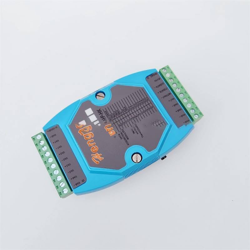
Figure 3.1: Front view of the I-7118DP-HK module. This image displays the module's blue casing, green terminal blocks for wiring, and a central label detailing input ranges and communication ports. The 'HengKe' brand is visible at the top.
The module's front panel (Figure 3.1) clearly labels the input and output terminals, as well as a table indicating various analog input ranges and corresponding codes. The device is housed in a durable casing suitable for industrial environments.
4. Setup and Installation
Follow these steps for proper installation of the I-7118DP-HK module:
4.1. Unpacking

Figure 4.1: The I-7118DP-HK module as received in its protective cardboard packaging.
- Carefully remove the module from its packaging (Figure 4.1).
- Inspect the module for any visible damage. If damage is found, do not proceed with installation and contact your supplier.
4.2. Mounting

Figure 4.2: Bottom view of the I-7118DP-HK module, highlighting the integrated DIN rail mounting mechanism.
- The module is designed for DIN rail mounting. Locate a suitable DIN rail within your control cabinet.
- Attach the module to the DIN rail by engaging the bottom clip (Figure 4.2) and pressing the module firmly until it clicks into place.
- Ensure the module is securely fastened and does not wobble.
4.3. Wiring
Refer to Figure 3.1 for terminal identification. Ensure all connections are secure and correct before applying power.
- Power Supply: Connect the appropriate DC power supply to the V+ and V- terminals. Observe polarity.
- Analog Inputs: Connect your sensors (e.g., thermocouples, voltage sources) to the designated input terminals (Vin+, Vin-, Vout+, Vout-). Refer to the module's label for specific channel assignments and input types.
- RS-485 Communication: Connect the RS-485 A (DATA+) and B (DATA-) lines to your host controller or communication network. Connect GND to the common ground.
- Address Setting: The module features an address setting mechanism (labeled 'ADD.' on the module). Configure the module's address as required by your communication protocol.
5. Operating Instructions
Once the module is installed and wired, you can proceed with operation.
5.1. Power On
- Apply power to the module. The power indicator (if present) should illuminate.
5.2. Data Acquisition
- The module will begin acquiring data from the connected analog sensors.
- The type of input (e.g., thermocouple, voltage) and its range are configured via the 'CODE' setting on the module's label. Ensure this matches your sensor type and expected signal range.
5.3. Communication
- Communicate with the module via the RS-485 interface using the appropriate protocol (e.g., Modbus RTU).
- Refer to the communication protocol documentation for details on reading data registers and configuring module parameters.
6. Maintenance
The I-7118DP-HK module is designed for low maintenance. However, periodic checks are recommended.
- Cleaning: Gently clean the exterior of the module with a soft, dry cloth. Do not use abrasive cleaners or solvents. Ensure power is off before cleaning.
- Connection Check: Periodically inspect all wiring connections for tightness and signs of corrosion or damage. Re-tighten terminals if necessary.
- Environmental Check: Ensure the operating environment remains within the specified temperature and humidity ranges.
7. Troubleshooting
If you encounter issues with the I-7118DP-HK module, refer to the following common problems and solutions:
| Problem | Possible Cause | Solution |
|---|---|---|
| Module does not power on. | No power supply, incorrect voltage, or reversed polarity. | Check power supply connections and voltage. Ensure correct polarity. |
| Incorrect analog readings. | Wrong input range setting, sensor malfunction, or wiring error. | Verify the 'CODE' setting matches the sensor type and range. Check sensor functionality and wiring. |
| RS-485 communication failure. | Incorrect wiring (A/B reversed), wrong module address, or communication settings mismatch. | Check RS-485 wiring (DATA+ and DATA-). Verify module address and communication parameters (baud rate, parity) in your host system. |
| Module is hot to the touch. | Overload or insufficient ventilation. | Check for short circuits or excessive load. Ensure adequate airflow around the module. |
8. Specifications
| Parameter | Value |
|---|---|
| Model | I-7118DP-HK |
| Brand | Generic |
| Display Type | Analog |
| Part Number | ZGZ_WJSN_10018 |
| Output Interface | RS-485 |
| Input Ranges (Voltage) | +/-15mV, +/-50mV, +/-100mV, +/-500mV, +/-1V, +/-2.5V, +/-5V, +/-10V |
| Input Ranges (Thermocouple) | Type J, K, T, E, R, S, B, N, C |
| ASIN | B0D7HQFR51 |
9. Warranty and Support
Specific warranty information for this Generic product is not provided in this manual. For warranty details, technical support, or service inquiries, please contact your original point of purchase or the manufacturer directly. Keep your purchase receipt as proof of purchase.