Diyeeni Car Amplifier Board KL 180
Instruction Manual
1. Introduction
This manual provides detailed instructions for the installation, operation, and maintenance of your Diyeeni Car Amplifier Board KL 180. This high-power 1000W subwoofer board is designed to enhance your car audio system, providing robust bass output for 8, 10, or 12-inch bass speakers. Please read this manual thoroughly before use to ensure proper setup and safe operation.
2. Safety Information
- Ensure all power connections are secure and correctly polarized to prevent damage to the amplifier or vehicle electrical system.
- Disconnect the vehicle's battery before performing any wiring or installation to avoid electrical shock or short circuits.
- Avoid exposing the amplifier board to moisture or extreme temperatures.
- Do not attempt to open or modify the amplifier board. Refer all servicing to qualified personnel.
- Ensure adequate ventilation around the amplifier to prevent overheating.
3. Package Contents
Verify that all items are present in the package:
- 1 x Car Amplifier Board
4. Product Overview
The Diyeeni Car Amplifier Board KL 180 features a robust design with an aluminum alloy casing for efficient heat dissipation and durable performance. It includes various input/output terminals and control knobs for sound adjustment.
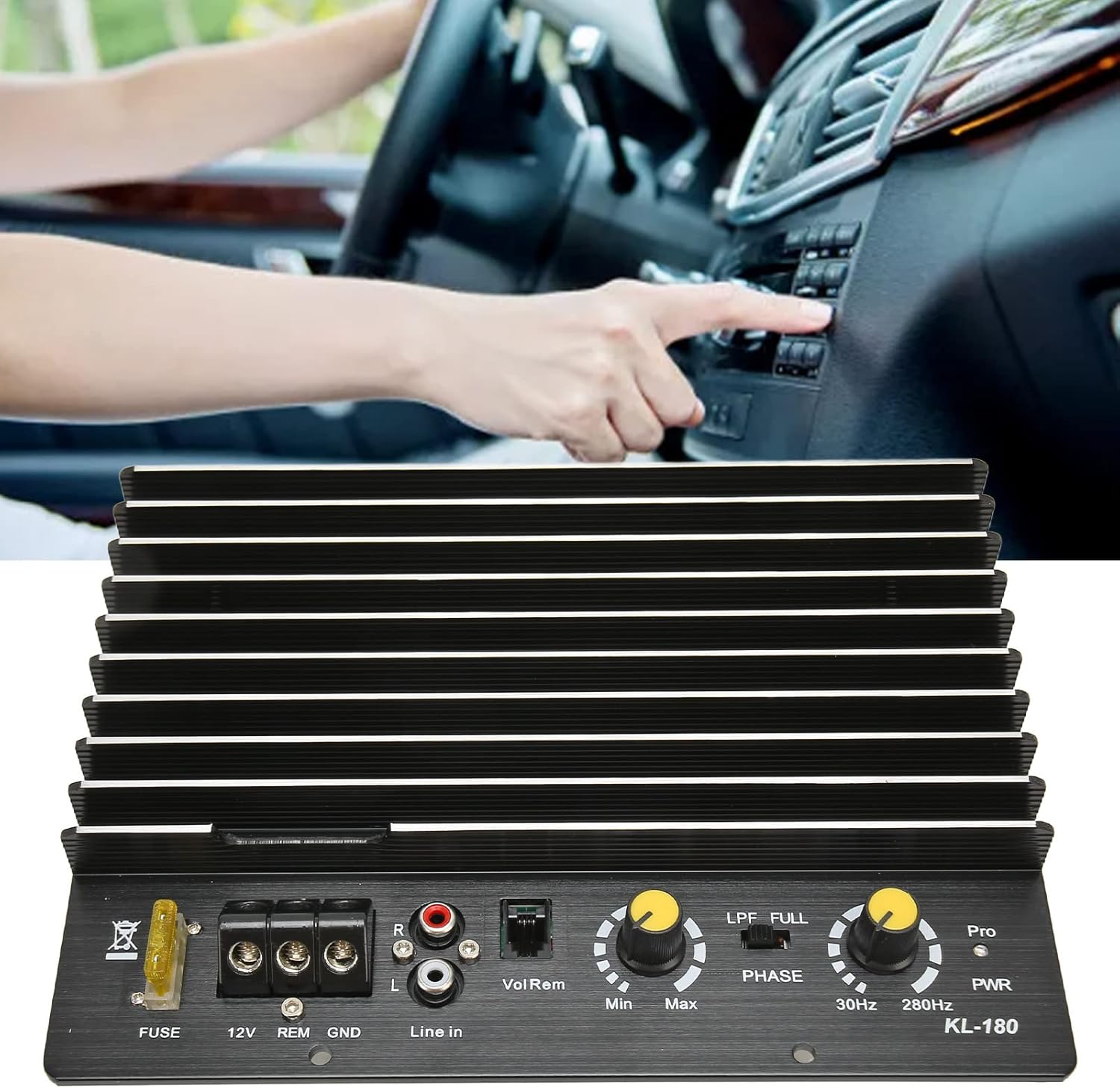
Figure 4.1: Front view of the Diyeeni Car Amplifier Board KL 180, showing the control panel with FUSE, 12V, REM, GND terminals, Line In (RCA), Vol Rem, LPF/FULL/PHASE switch, 30Hz-280Hz frequency knob, and PWR indicator. The heat sink fins are prominent.

Figure 4.2: Angled view of the amplifier board, emphasizing its premium aluminum alloy material and powerful heat dissipation fins, designed for durability and long-lasting performance.

Figure 4.3: Top-down view of the amplifier board with the cover removed, revealing the internal circuit board (A-800 20230310) with various electronic components, capacitors, resistors, and wiring connections.
5. Specifications
| Parameter | Value |
|---|---|
| Item Type | Car Amplifier Board |
| Material | Aluminum Alloy |
| Model | KL 180 |
| Impedance | 4Ω |
| THD (Total Harmonic Distortion) | Less Than 0.1% |
| Frequency Response | 20Hz-250KHz |
| Power Output | 1000W (Peak) |
| Power Supply | 12V DC |
| Item Weight | 1.92 pounds |
| Package Dimensions | 8.66 x 7.09 x 2.36 inches |
| Item Model Number | Diyeenikxgyw4fte9 |
6. Installation and Wiring
Proper installation is crucial for optimal performance and safety. Follow these steps carefully.
6.1 Speaker Requirements
- This amplifier board supports 8, 10, or 12-inch bass speakers.
- For 8-inch or 10-inch speakers, a 4-8Ω impedance and 120-170 magnetic strength are recommended.
- For 12-inch speakers, a 4-8Ω impedance and 140 magnetic strength (or below) are recommended.
- Ensure speaker output wires do not short circuit (touch each other).
- Ensure speaker output wires do not touch the amplifier's heat sink/radiator.
- Prevent any exposed part of the circuit board from contacting metal objects.
- Speaker connection: Use the pre-soldered red and black wires on the back of the amplifier board. Connect the red wire to the speaker's positive (+) terminal and the black wire to the speaker's negative (-) terminal.
6.2 Power and Audio Wiring Diagram

Figure 6.1: Wiring diagram for the amplifier board. Top diagram shows power connections: 12V to positive battery (with a fuse within 30cm/11.8in of the battery), REM to ACC wire (control speaker power switch), GND to negative battery/chassis ground (ensure paint is polished off for good contact). Bottom diagram shows sound output connection from the host (navigation or CD player) to the amplifier's left and right sound input. If the original host lacks left/right sound output, a high-to-low converter is required.
Note: For home use, a separate 220V to 12V 15A transformer or higher is required. Power wiring for home use: 12V and REM connect together to the positive terminal, GND to the negative terminal of the 12V power supply.
6.3 Power Supply and Wiring Methods
- With Car CD Player:
- GND: Connect to the negative side of the car power supply.
- 12V: Connect to the positive side of the 12V power supply.
- REM: Connect to the CD player control wire. This allows the CD player to directly control the subwoofer amplifier's on/off state.
- Without Car CD Player (Manual Control):
- GND: Connect to the negative side of the car power supply.
- +12V and REM: Connect together to the positive side of the 12V power supply. You can also install a separate switch between 12V and REM to manually control the amplifier's power.
- Direct Battery Connection (Always On):
- GND: Connect to the negative terminal of the battery.
- +12V and REM: Connect together to the positive terminal of the 12V battery. Note that this method will keep the amplifier powered on continuously, potentially draining the battery if not managed.
- Household Use:
- A separate power converter (220V AC to 12V DC, 15A or higher) is required.
- You may need to modify the converter's output plug or use a DC socket to create an adapter cable for connection to the amplifier's 12V, REM, and GND terminals as described in the note above.
6.4 Installation Methods for Subwoofer Control

Figure 6.2: Three installation methods for controlling the subwoofer:
Method 1 (Subwoofer not controlled by car key): Direct connection of +12V, REM, and GND to the car battery. Sound input from the car CD player. The amplifier remains on independently of the car's ignition.
Method 2 (Car key control subwoofer switch on and off): +12V and REM connected to the car battery, with REM also connected to a key head signal (ACC) for ignition-controlled power. Sound input from the car CD player. The amplifier turns on/off with the car's ignition.
Method 3 (Original CD player audio sent into the subwoofer): Similar to Method 2 for power, but specifically highlights the audio signal path from the original CD player to the subwoofer amplifier, ensuring the amplifier receives the audio signal from the head unit.
7. Operation
Once installed, the amplifier board offers several controls for fine-tuning your audio experience.
Figure 7.1: Control panel of the Diyeeni Car Amplifier Board KL 180.
- Vol Rem (Volume Remote): Adjusts the overall output volume of the amplifier. Turn clockwise to increase volume, counter-clockwise to decrease.
- LPF / FULL / PHASE Switch: This switch selects the operating mode for the audio output.
- LPF (Low Pass Filter): Engages the low-pass filter, allowing only low frequencies to pass to the subwoofer. Use this setting in conjunction with the 30Hz-280Hz knob to set the desired cutoff frequency for bass.
- FULL: Bypasses the filter, allowing the full frequency range to pass through the amplifier. This setting is typically not used for subwoofers.
- PHASE: Adjusts the phase of the subwoofer output. This can help blend the subwoofer's sound with the main speakers, preventing cancellation or reinforcement issues. Experiment with this setting to achieve the best sound integration.
- 30Hz-280Hz Knob: When the LPF mode is selected, this knob sets the low-pass filter cutoff frequency. Frequencies above this setting will be attenuated, ensuring only the desired bass frequencies are sent to the subwoofer.
- PWR (Power) Indicator: This LED illuminates when the amplifier is powered on and receiving a signal.
8. Maintenance
- Keep the amplifier clean and free from dust. Use a soft, dry cloth for cleaning.
- Ensure the heat sink fins are not obstructed to maintain proper cooling and prevent overheating.
- Regularly check all wiring connections for tightness and corrosion to ensure optimal performance and safety.
- If the fuse blows, replace it with a fuse of the same type and rating to prevent damage to the amplifier or vehicle electrical system.
9. Troubleshooting
- No Power: Check the 12V, GND, and REM connections. Ensure the fuse is intact. Verify the car battery has sufficient charge.
- No Sound: Check audio input connections (Line In). Ensure speakers are correctly wired and functional. Verify volume settings on both the amplifier and the head unit.
- Distorted Sound: Reduce the volume level. Check speaker impedance compatibility. Ensure all connections are secure and free from interference.
- Overheating: Ensure adequate ventilation around the amplifier. Check for obstructions to the heat sink fins. Reduce prolonged high-volume operation.
10. Warranty and Support
For warranty information or technical support, please refer to the seller's policies or contact Diyeeni customer service through their official channels. Keep your purchase receipt for warranty claims.
For further assistance, visit the Diyeeni Store on Amazon.


