1. Introduction
This instruction manual provides essential information for the safe and efficient use of your Enpower MC3336 Control Unit. This unit is designed for compatibility with EV US Moke vehicles and Marshall Golf Carts, serving as a robust AC motor controller. Please read this manual thoroughly before installation and operation to ensure proper function and to prevent damage or injury. Keep this manual for future reference.
2. Safety Information
Always observe the following safety precautions to reduce the risk of electric shock, fire, or injury:
- Ensure the power supply is disconnected before performing any installation, maintenance, or troubleshooting.
- Only qualified personnel should install and service this control unit.
- Wear appropriate personal protective equipment (PPE), including insulated gloves and eye protection.
- Verify all connections are secure and correctly polarized to prevent short circuits.
- Do not expose the control unit to moisture, extreme temperatures, or corrosive environments.
- Refer to the vehicle's specific wiring diagrams and safety guidelines in conjunction with this manual.
3. Product Overview
The Enpower MC3336 is an advanced control unit designed to manage the AC motor in compatible electric vehicles. It features robust construction and precise control capabilities.

Figure 3.1: The Enpower MC3336 Control Unit, showcasing its compact design and prominent Enpower branding. This image highlights the unit's exterior and overall form factor.

Figure 3.2: A view of the Enpower MC3336 Control Unit with its integrated wiring harness. This image illustrates the various connection points and the robust cabling designed for vehicle integration.

Figure 3.3: An overhead perspective of the Enpower MC3336 Control Unit, providing a clear view of its top surface and mounting points. This angle helps in understanding its physical dimensions and installation orientation.
4. Setup and Installation
4.1. Pre-Installation Checklist
- Verify the control unit model (MC3336) matches your vehicle's requirements.
- Ensure all necessary tools and connectors are available.
- Confirm the vehicle's battery is disconnected and secured.
4.2. Mounting the Control Unit
- Select a secure, dry, and well-ventilated location within the vehicle, away from direct heat sources or excessive vibration.
- Use appropriate fasteners to mount the control unit firmly to the vehicle chassis. Ensure there is adequate clearance for wiring and cooling.
4.3. Wiring Connections
Follow the vehicle manufacturer's wiring diagram and the specific instructions provided with the control unit. Pay close attention to:
- Power Connections: Connect the main battery positive and negative terminals to the corresponding terminals on the control unit. Use appropriately gauged wires and fuses.
- Motor Connections: Connect the AC motor phases (U, V, W) to the control unit's motor output terminals.
- Signal Connections: Connect throttle input, brake switch, reverse switch, and other auxiliary signals as per the vehicle's specifications.
- Communication Ports: If applicable, connect diagnostic tools or communication interfaces.

Figure 4.1: A digital interface displaying various MC-STATE parameters such as output current, motor speed, controller temperature, motor temperature, battery voltage, and fault messages. This interface is crucial for monitoring the control unit's real-time performance and diagnosing issues.
5. Operating Instructions
5.1. Initial Power-Up
- After all connections are made and verified, reconnect the vehicle's battery.
- Turn the vehicle's ignition key to the 'ON' position.
- Observe any indicator lights on the control unit or vehicle dashboard for status or error codes.
5.2. Basic Operation
Once the control unit is powered and initialized, the vehicle should be ready for operation. Use the accelerator pedal to control motor speed and the brake pedal to slow down or stop.
5.3. Parameter Adjustment and Monitoring
The control unit may allow for parameter adjustments and real-time monitoring via a compatible diagnostic tool or software interface. Key parameters include:
- F-DATA (Function Data): Adjustments for acceleration profiles (initial, second, astern), deceleration rates, and braking characteristics.
- MC-STATE (Motor Controller State): Real-time monitoring of output current, motor speed, controller temperature, motor temperature, battery voltage, and fault messages.

Figure 5.1: A software interface displaying F-DATA parameters for the control unit. This screen allows users to configure settings such as initial acceleration, second acceleration, acceleration of astern, deceleration, brake reduction speed, and speed KP/KI values, enabling fine-tuning of vehicle performance.
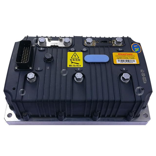
Figure 5.2: A diagnostic tool or status indicator displaying operational status with Enpower branding. This device provides visual feedback on the control unit's condition, often using LED indicators to show power, communication, or error states.
6. Maintenance
Regular maintenance ensures the longevity and optimal performance of your Enpower MC3336 Control Unit.
- Periodic Inspection: Visually inspect the control unit and its wiring for any signs of wear, corrosion, or damage. Check for loose connections.
- Cleaning: Keep the control unit free from dust, dirt, and debris. Use a soft, dry cloth for cleaning. Do not use harsh chemicals or solvents.
- Ventilation: Ensure that the area around the control unit remains clear to allow for proper airflow and heat dissipation.
- Software Updates: Check with the manufacturer or authorized service centers for any available firmware updates that may improve performance or address known issues.
7. Troubleshooting
This section provides solutions for common issues you might encounter. For complex problems, contact technical support.
| Problem | Possible Cause | Solution |
|---|---|---|
| Vehicle does not power on | Disconnected battery, blown fuse, faulty ignition switch | Check battery connections, inspect fuses, test ignition switch. |
| Motor does not respond to throttle | Faulty throttle sensor, wiring issue, control unit error | Verify throttle sensor operation, check wiring continuity, consult diagnostic tool for error codes. |
| Intermittent power loss | Loose connections, overheating, low battery voltage | Tighten all power connections, ensure proper ventilation, check battery charge level. |
| Unusual noises from motor/controller | Motor fault, mechanical issue, control unit malfunction | Inspect motor for damage, check for obstructions, contact support if control unit is suspected. |
8. Specifications
Key technical specifications for the Enpower MC3336 Control Unit:
| Feature | Detail |
|---|---|
| Model Number | MC3336 |
| Brand | Enpower (Generic) |
| Material | Other (Specific material not detailed) |
| Manufacturer Reference | ML2-1005005483916926-001 |
| ASIN | B0D73NG93V |
| First Available Date | June 14, 2024 |
9. Warranty Information
All Enpower MC3336 Control Units come with a 12-month warranty from the date of purchase. This warranty covers manufacturing defects and material failures under normal use. It does not cover damage caused by improper installation, misuse, accidents, or unauthorized modifications. Please retain your proof of purchase for warranty claims.
10. Support
Should you encounter any problems with your Enpower MC3336 Control Unit, such as damaged products or incorrect items, please do not hesitate to contact us. We are committed to providing prompt assistance and will respond to your inquiries within 24 hours. For technical support or warranty claims, please reach out through the platform where the product was purchased or refer to the contact information provided with your product packaging.


