1. Product Overview
The Micsig ETO Series Tablet Oscilloscopes (models ETO3504 and ETO5004) are advanced portable measurement instruments designed for professional use in laboratories and field environments. These devices feature a 14-inch integrated touch screen, a large-capacity battery, and a multi-tasking operating system, providing a comprehensive solution for waveform analysis.
Key features include:
- Up to 500MHz bandwidth and 3GSa/s sampling rate.
- 4 analog channels for multi-signal analysis.
- 360Mpts memory depth for extended waveform capture.
- 14-inch, 1920x1200 resolution touch screen display.
- Integrated 13,500mAh Li-ion battery for portable operation.

Figure 1.1: Micsig ETO Series Tablet Oscilloscope in operation, displaying multiple waveforms.
2. Initial Setup
2.1 Unpacking and Inspection
Carefully remove the oscilloscope and all accessories from the packaging. Inspect for any signs of damage. Retain the packaging for future transport or storage.
2.2 Powering On and Charging
The device includes a 13,500mAh Lithium Metal battery. Before first use, it is recommended to fully charge the battery using the provided power adapter. Connect the power adapter to the device's power input and then to a suitable power outlet. The charging indicator will show the charging status.
2.3 Connecting Probes and Accessories
The ETO series features 4 analog channels. Connect your probes to the BNC connectors on the device. The Mic-OPI™ probe interface automatically matches probe attenuation, simplifying setup. Ensure all connections are secure.

Figure 2.1: Overview of the oscilloscope's rear panel, showing the battery compartment, VESA mounting points, and various interfaces including USB, HDMI, and probe connections.
2.4 Interface Overview
The oscilloscope is equipped with various interfaces for connectivity and expansion:
- USB 3.0/2.0 Host: For connecting external storage devices or peripherals.
- USB Device (Type-C): For PC connection and data transfer.
- HDMI: For external display output.
- Trigger Out: For external triggering.
- Grounding Socket: For safety grounding.
- Mic-OPI™ Probe Interface: For intelligent probe detection and compensation.
3. Operating Instructions
3.1 User Interface and Touch Control
The ETO series features an intuitive operating interface designed for ease of use. The 14-inch full touch-capacitive display allows for direct interaction with waveforms and settings. Use gestures such as pinch-to-zoom, drag-to-pan, and tap-to-select for efficient operation.
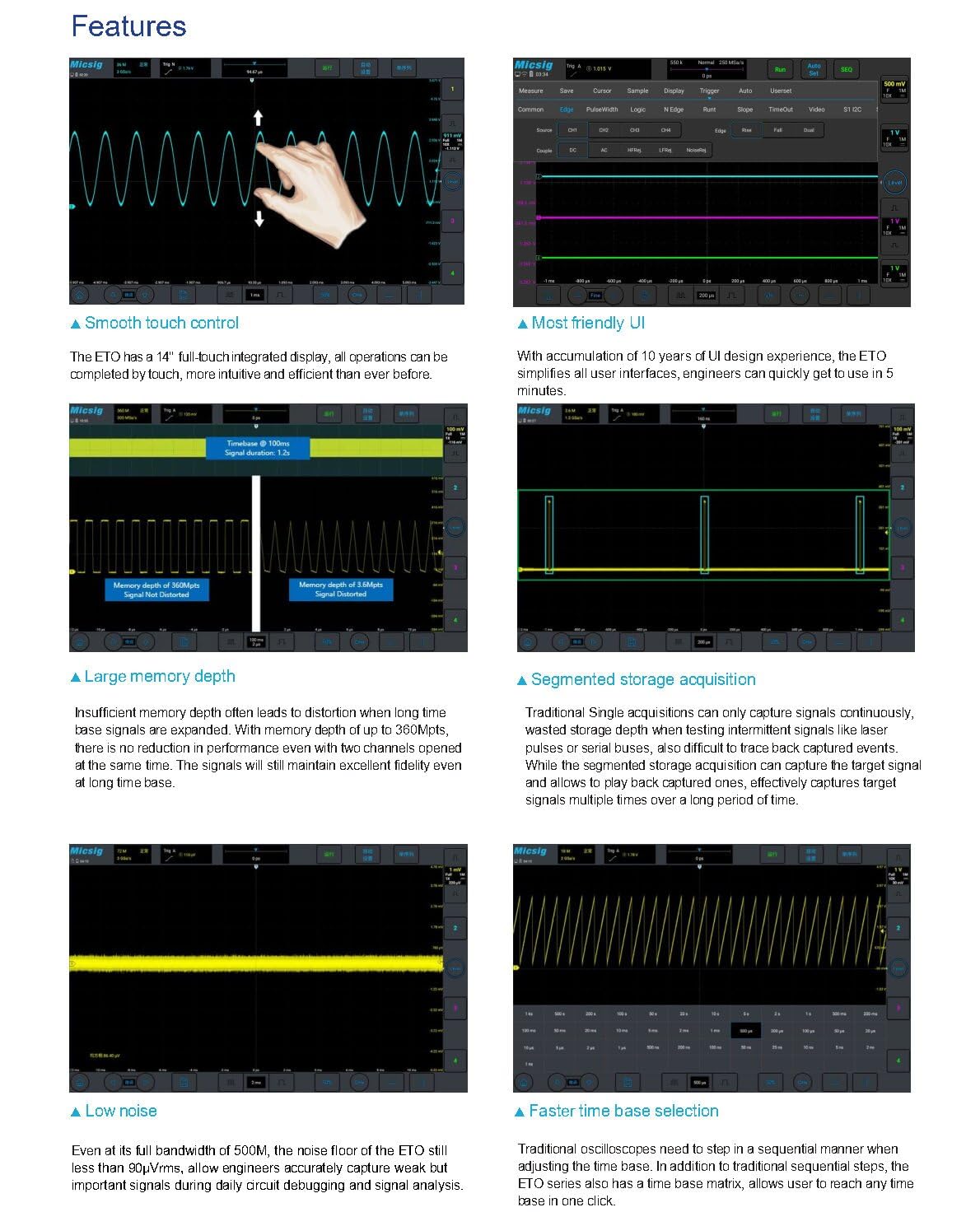
Figure 3.1: Demonstrates smooth touch control for waveform manipulation, intuitive user interface, large memory depth, segmented storage, low noise, and faster time base selection.
3.2 Basic Measurements
After connecting your probes and powering on the device, you can begin taking measurements. Adjust the vertical scale (Volts/Div) and horizontal time base (Sec/Div) using the on-screen controls or physical knobs (if available on your model). The oscilloscope automatically displays key waveform parameters.
3.3 Advanced Features
- Hardware Digital Filtering: Apply high-pass or low-pass filters to isolate specific frequency components of a signal.
- Serial Bus Decoding and Analysis: Supports various serial bus protocols including RS-232/422/485, UART, CAN, CAN FD, LIN, SPI, I2C, and ARINC-429, MIL-STD-1553B. Decoded data can be exported to CSV format.
- Multiple Trigger Functions: Offers various trigger types such as edge, pulse width, logic, Nth edge, runt, slope, bus, window, and interval to capture specific events.
- Statistics Measurement: Automatically calculates average, maximum, minimum, and root mean square (RMS) values for up to 50,000 waveform events.
- Advanced Math Functions: Includes addition, subtraction, multiplication, division, integration, differentiation, and FFT (Fast Fourier Transform) for detailed signal analysis.
- Diverse File Saving: Save waveforms and measurement results in binary (.BIN) or CSV format. Images can also be saved.
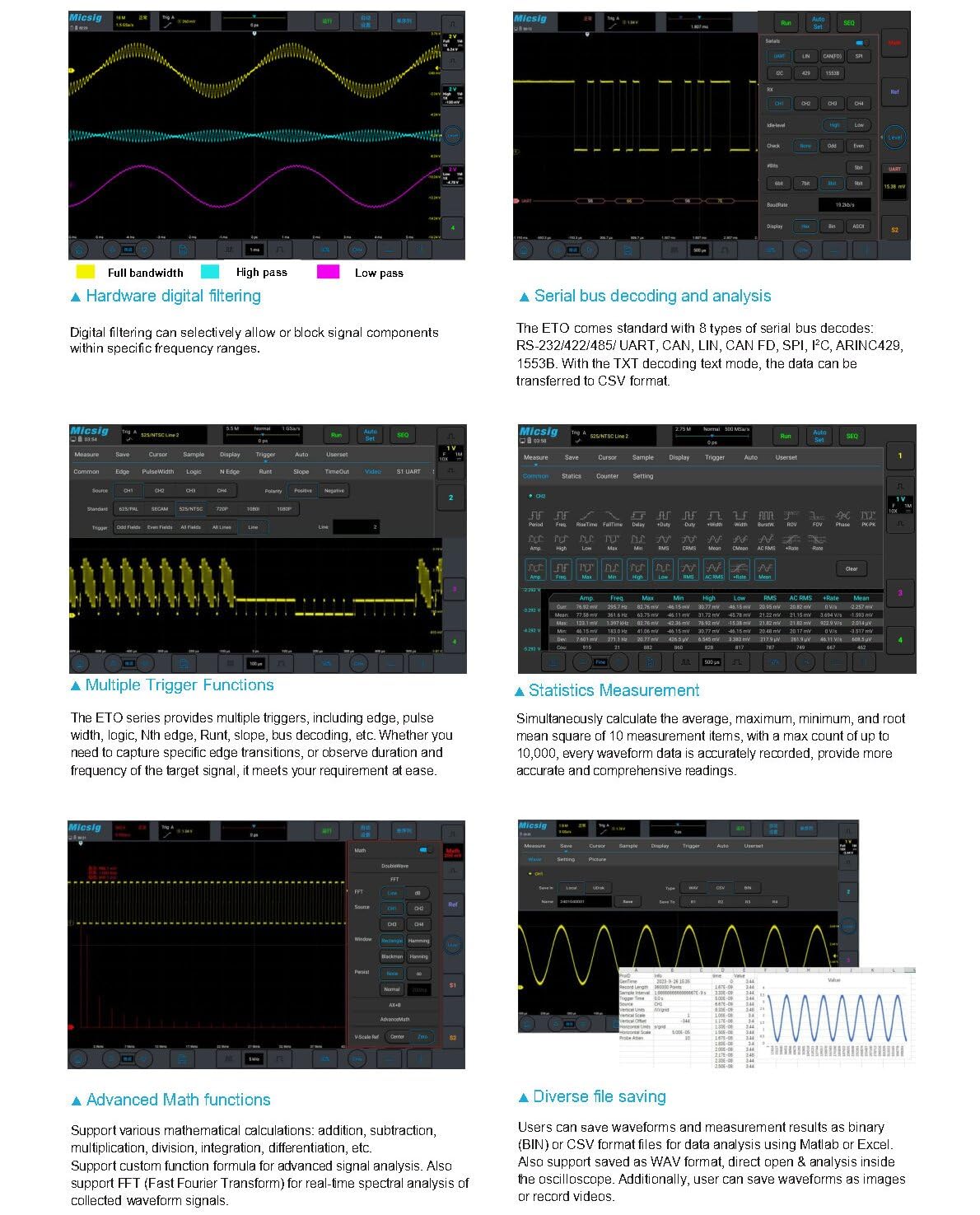
Figure 3.2: Illustrates hardware digital filtering, serial bus decoding, multiple trigger functions, statistics measurement, advanced math functions, and diverse file saving options.
3.4 Remote Control
The ETO series supports remote control via PC software, mobile applications, and HDMI screen projection. This allows for flexible operation and data analysis from a distance, enhancing efficiency in various testing scenarios.
4. Technical Specifications
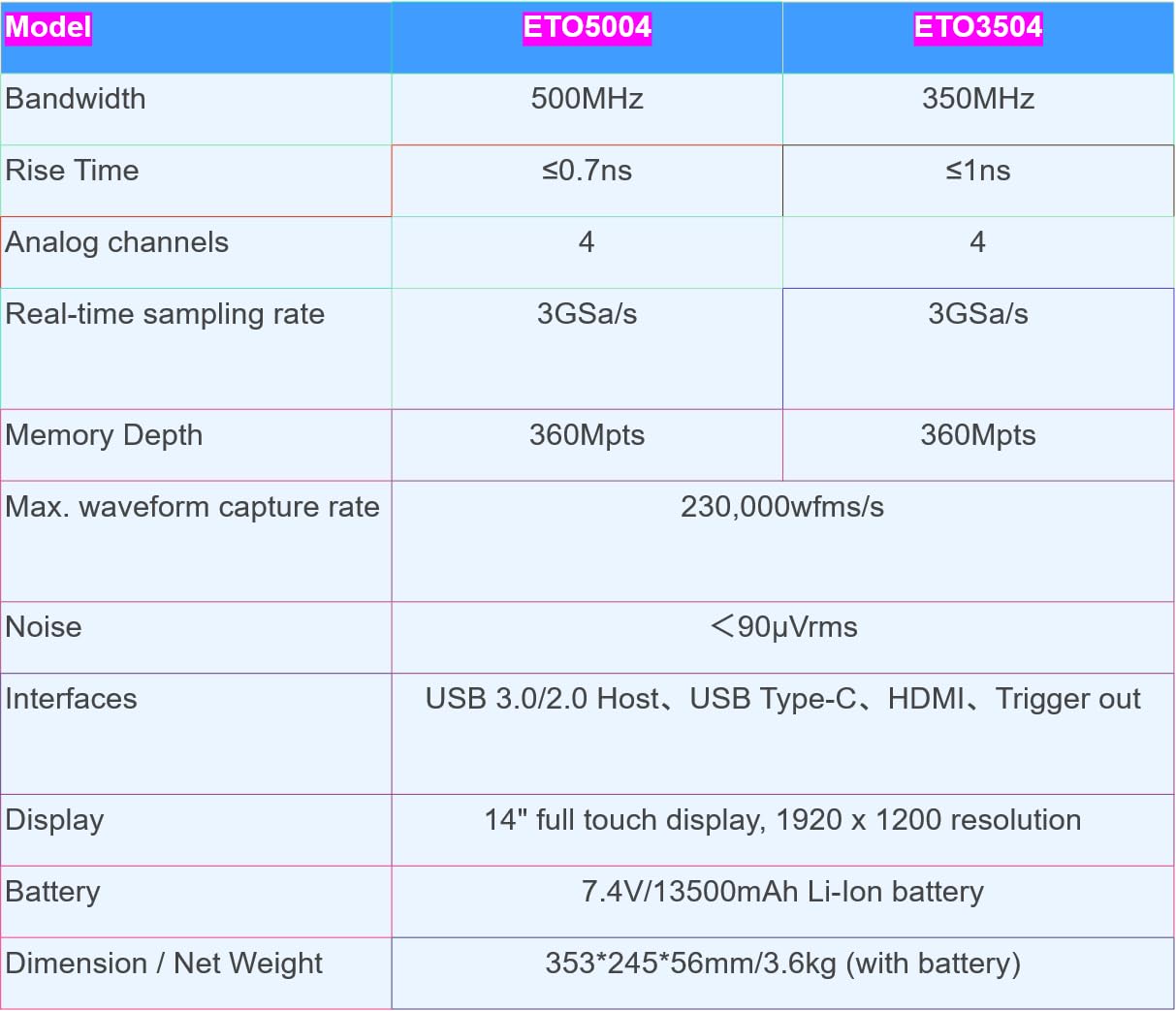
Figure 4.1: Detailed specifications for ETO5004 and ETO3504 models.
| Feature | ETO5004 | ETO3504 |
|---|---|---|
| Bandwidth | 500MHz | 350MHz |
| Rise Time | ≤0.7ns | ≤1ns |
| Analog Channels | 4 | 4 |
| Real-time Sampling Rate | 3GSa/s | 3GSa/s |
| Memory Depth | 360Mpts | 360Mpts |
| Max. Waveform Capture Rate | 230,000wfms/s | |
| Noise Floor | <90µVrms | |
| Interfaces | USB 3.0/2.0 Host, USB Type-C, HDMI, Trigger out | |
| Display | 14 inches, 1920 x 1200 resolution, full touch | |
| Battery | 7.4V/13,500mAh Li-ion battery (included) | |
| Dimensions / Net Weight | 353*245*56mm / 3.6kg (with battery) | |
| Item Model Number | SM-ETO5004 | SM-ETO3504 |
5. Maintenance
5.1 Cleaning
To clean the device, use a soft, damp cloth. Avoid abrasive cleaners, solvents, or strong chemicals that could damage the screen or casing. Ensure the device is powered off and disconnected from all power sources before cleaning.
5.2 Battery Care
For optimal battery life, avoid fully discharging the battery frequently. Store the device in a cool, dry place when not in use for extended periods. If storing for a long time, ensure the battery is charged to approximately 50% to prevent deep discharge.
5.3 Environmental Conditions
Operate and store the oscilloscope within the specified environmental ranges (temperature, humidity) to ensure proper function and longevity. Avoid exposure to extreme temperatures, direct sunlight, dust, and moisture.
6. Troubleshooting
If you encounter issues with your Micsig ETO series oscilloscope, consider the following basic troubleshooting steps:
- No Power: Ensure the power adapter is securely connected and the battery is charged. Check the power switch.
- No Signal Display: Verify that probes are correctly connected to the input channels and the signal source. Check probe attenuation settings. Adjust vertical and horizontal scales.
- Unstable Waveform: Adjust the trigger level and trigger source. Ensure the trigger mode is appropriate for the signal.
- Touch Screen Unresponsive: Restart the device. If the issue persists, contact customer support.
- Connectivity Issues: For USB or HDMI connections, ensure cables are properly seated and drivers (if applicable for PC software) are installed.
For more complex issues, refer to the detailed troubleshooting guide available on the Micsig official website or contact customer support.
7. Warranty and Support
This product is manufactured by Shenzhen Micsig Technology Co., Ltd. For specific warranty information, please refer to the warranty card included with your product or visit the official Micsig website. Warranty terms typically cover manufacturing defects for a specified period from the date of purchase.
For technical support, service, or inquiries, please contact the Micsig Official Store or the manufacturer directly. Contact information can usually be found on the product packaging or the official Micsig website.
Manufacturer: Shenzhen Micsig Technology Co., Ltd.
Seller: Micsig Official Store


