1. Introduction
This user manual provides essential information for the installation, operation, and maintenance of the Coolmay MX3G-32MRT PLC Module. This Programmable Logic Controller (PLC) module is designed for industrial automation applications, offering reliable control and data processing capabilities. It features 16 digital inputs, 16 transistor sink outputs, and 2 analog inputs, making it suitable for a wide range of control tasks.
2. Safety Information
Always observe the following safety precautions to prevent personal injury and damage to the equipment:
- Ensure all power is disconnected before installation, wiring, or maintenance.
- Installation and wiring should only be performed by qualified personnel.
- Proper grounding is essential to prevent electrical shock and ensure stable operation.
- Do not operate the module in environments exceeding its specified temperature, humidity, or vibration limits.
- Avoid exposing the module to direct sunlight, corrosive gases, or excessive dust.
3. Product Overview
The Coolmay MX3G-32MRT PLC Module is a compact and robust industrial control device. It integrates various components for seamless operation within an automation system.
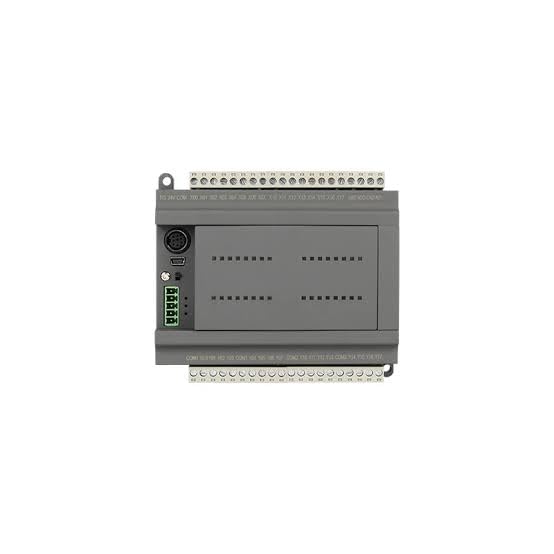
Figure 3.1: Top View of MX3G-32MRT PLC Module. This image displays the top-down perspective of the PLC module, highlighting the clearly labeled input and output terminal blocks at the top and bottom. Various communication ports, including a USB port, are visible on the left side, along with status indicator LEDs.
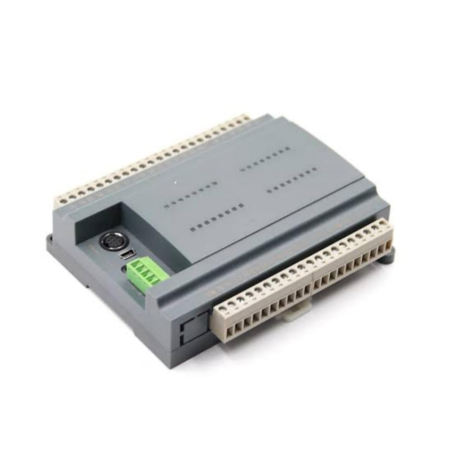
Figure 3.2: Angled View of MX3G-32MRT PLC Module. This image provides an angled view of the PLC module, showcasing its compact and sturdy grey casing. The perspective allows for a better understanding of its overall dimensions and the arrangement of its side-mounted connectors and terminal blocks.
Key Components:
- Digital Input Terminals: For connecting sensors and switches.
- Transistor Sink Output Terminals: For controlling actuators and indicators.
- Analog Input Terminals: For connecting analog sensors.
- Power Input: For connecting the DC power supply.
- Communication Ports: For programming and data exchange with other devices.
- Status Indicators: LEDs to show power, run, and error status.
4. Setup
4.1. Mounting
The MX3G-32MRT module is designed for DIN rail mounting. Securely attach the module to a standard DIN rail in a control cabinet, ensuring adequate ventilation space around the unit.
4.2. Wiring
Follow these general guidelines for wiring the PLC module:
- Power Supply: Connect a stable DC power supply to the designated power input terminals. Observe correct polarity.
- Digital Inputs: Connect your digital input devices (e.g., push buttons, limit switches) to the digital input terminals. Refer to the module's specific wiring diagram for input type (sink/source) compatibility.
- Transistor Sink Outputs: Connect your output devices (e.g., relays, indicator lights) to the transistor sink output terminals. Ensure the load current does not exceed the specified maximum for each output.
- Analog Inputs: Connect analog sensors (e.g., temperature, pressure) to the analog input terminals. Ensure proper signal type and range matching.
- Grounding: Connect the module's ground terminal to a reliable earth ground.
4.3. Initial Connection
Connect the PLC module to a computer using a compatible programming cable via the designated communication port. Install the necessary drivers and programming software on your computer.
5. Operating Instructions
5.1. Powering On
After completing all wiring and connections, apply power to the PLC module. The power indicator LED should illuminate, indicating successful power-up.
5.2. Programming
Use the compatible programming software to develop and download your control logic program to the PLC. The software provides an environment for creating ladder logic, function block diagrams, or other programming languages supported by the module.
5.3. Run Mode
Once the program is downloaded, switch the PLC to RUN mode (either via software or a physical switch if available). The PLC will then execute the loaded program, controlling the connected inputs and outputs according to the logic.
5.4. Monitoring
The programming software allows for real-time monitoring of input/output status, internal registers, and program execution. This is crucial for debugging and verifying system operation.
6. Maintenance
Regular maintenance ensures the longevity and reliable operation of your PLC module:
- Cleaning: Periodically clean the module and its surroundings to prevent dust accumulation, which can lead to overheating or short circuits. Use a soft, dry cloth. Do not use solvents.
- Environmental Control: Ensure the operating environment remains within the specified temperature and humidity ranges.
- Connection Checks: Periodically inspect all wiring connections for tightness and signs of corrosion or damage.
- Firmware Updates: Check the Coolmay official website for any available firmware updates that may improve performance or add new features. Follow the provided instructions carefully for any update procedures.
7. Troubleshooting
If you encounter issues with your MX3G-32MRT PLC Module, refer to the following common problems and solutions:
| Problem | Possible Cause | Solution |
|---|---|---|
| PLC does not power on. | No power supply; incorrect wiring; faulty power supply. | Check power connections and voltage; verify power supply functionality. |
| Inputs not responding. | Incorrect wiring; faulty sensor; program logic error. | Verify input wiring; test sensor functionality; check program logic. |
| Outputs not activating. | Incorrect wiring; faulty actuator; program logic error; overloaded output. | Verify output wiring; test actuator; check program logic; ensure load is within specifications. |
| Communication error with PC. | Incorrect cable; driver issue; wrong communication settings. | Ensure correct cable is used; reinstall drivers; verify communication parameters in software. |
| PLC in ERROR state (Error LED on). | Program error; hardware fault. | Check error codes in programming software; review program for errors; contact support if hardware fault suspected. |
If the problem persists after attempting these solutions, contact Coolmay customer support for further assistance.
8. Specifications
| Attribute | Detail |
|---|---|
| Brand | Coolmay |
| Model Number | MX3G-32MRT |
| Manufacturer | Shenzhen Coolmay Technology Co., Ltd |
| Country of Origin | China |
| Digital Inputs | 16 |
| Digital Outputs | 16 (Transistor Sink Type) |
| Analog Inputs | 2 |
| Number of Memory Sticks | 1 |
| ASIN | B0D69LG89H |
| First Available Date | 6 June 2024 |
9. Warranty and Support
For warranty information, please refer to the documentation provided with your purchase or contact your vendor. Coolmay products are designed for reliability, and customer satisfaction is a priority.
For technical support, troubleshooting assistance, or inquiries regarding the Coolmay MX3G-32MRT PLC Module, please visit the official Coolmay website or contact their customer service department. Ensure you have your product model number and any relevant purchase details ready when seeking support.


