Introduction
The XTUGA MT8 is an 8-channel UHF wireless microphone system designed for various audio applications, including singing, karaoke, church events, weddings, and DJ performances. This system features a durable metal build, stable signal transmission, and crystal-clear sound quality. This manual provides essential information for proper setup, operation, and maintenance of your wireless microphone system.
Key features include:
- UHF design with 4 professional antennas for high frequency stability.
- PLL digital phase-locked loop multi-channel frequency synthesis technology for minimal interference.
- Super pickup design and excellent signal-to-noise ratio for clear audio.
- Reliable line-of-sight operation range up to 230ft (70m).
- Automatic frequency scan function to avoid interference.
- Independent volume control for each microphone.
- LED LCD display for real-time monitoring of working parameters.
- Multiple output options: 1 XLR, 1 MIX, and 8 audio outputs.
Package Contents
Please verify that all items listed below are included in your package:

Image: XTUGA MT8 Product List. This image displays the complete contents of the MT8 package, including the main receiver unit, eight handheld wireless microphones (transmitters), five screws, two angle codes, an audio line cable, a power supply adapter, the user manual, and the product packaging.
- 1 x UHF Wireless Receiver
- 8 x Handheld Wireless Microphones (Transmitters)
- 5 x Screws
- 2 x Angle Codes (Mounting Brackets)
- 1 x Audio Line Cable
- 1 x Power Supply Adapter
- 1 x User Manual
Components Overview
UHF Wireless Receiver
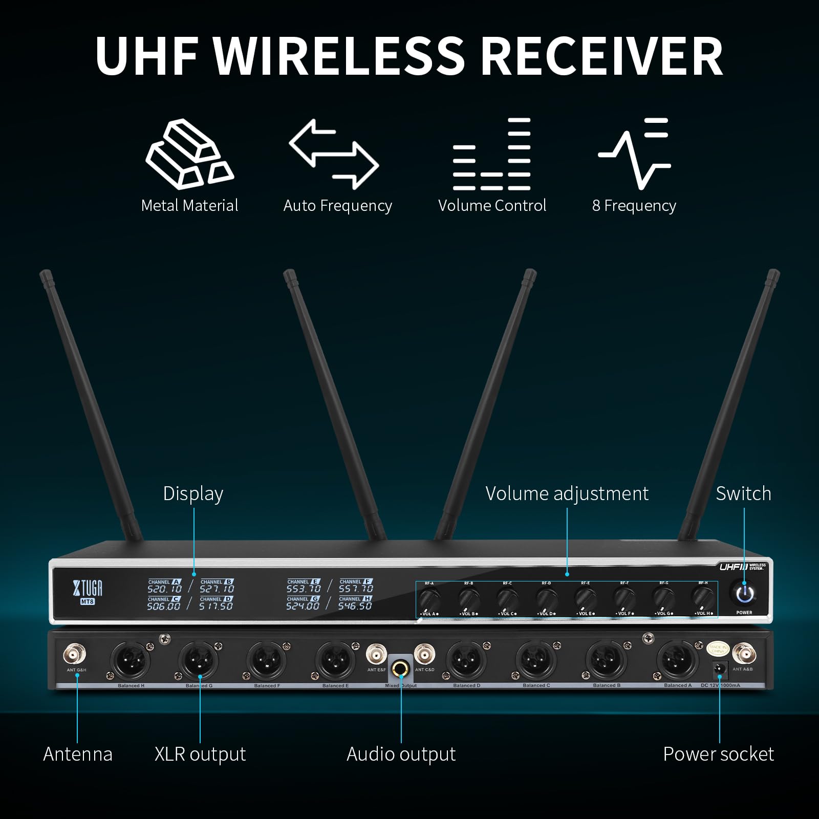
Image: UHF Wireless Receiver Diagram. This diagram highlights the key components of the receiver unit, including the antennas for signal reception, XLR and audio outputs for connecting to sound systems, the power socket, the display screen showing channel information, individual volume adjustment knobs, and the power switch.
The receiver unit is the central hub of your wireless microphone system. It features:
- Antennas: Four professional antennas for optimal signal reception.
- Display: LED LCD screen showing channel frequencies and other operational parameters.
- Volume Adjustment: Individual knobs for each of the 8 channels to control microphone volume.
- XLR Output: Balanced XLR outputs for professional audio connections.
- Audio Output: Mixed audio output for general connections.
- Power Socket: For connecting the power adapter.
- Power Switch: To turn the receiver on or off.
Handheld Wireless Microphone (Transmitter)
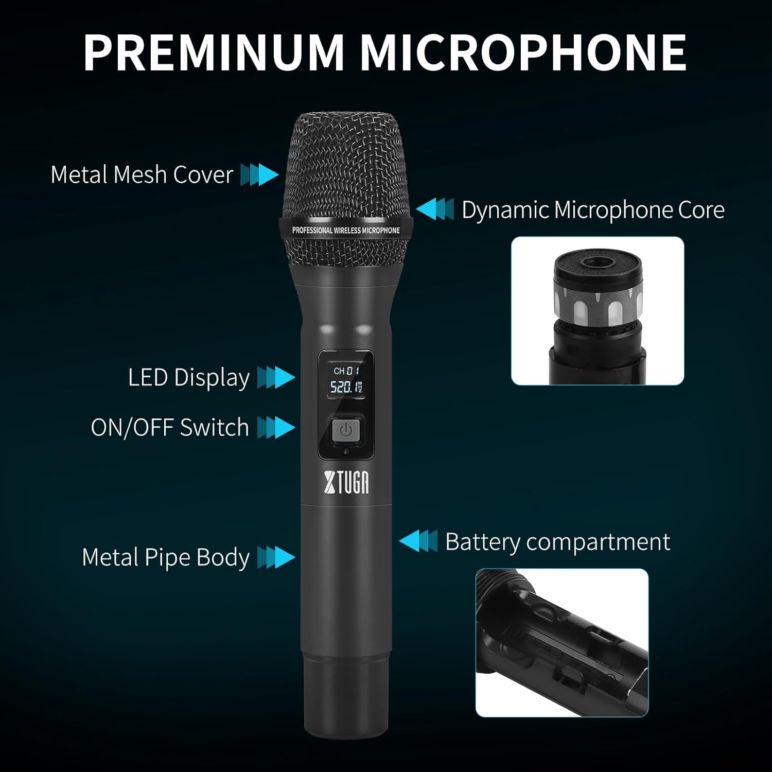
Image: Premium Microphone Diagram. This image details the construction of the handheld microphone, showing its metal mesh cover, dynamic microphone core, LED display for channel and battery status, ON/OFF switch, durable metal pipe body, and the battery compartment.
Each handheld microphone is a robust transmitter with the following features:
- Metal Mesh Cover: Protects the microphone capsule.
- Dynamic Microphone Core: Captures clear audio.
- LED Display: Shows current channel and battery status.
- ON/OFF Switch: To power the microphone on or off.
- Metal Pipe Body: Ensures durability and a professional feel.
- Battery Compartment: Houses the batteries required for operation.
Setup Instructions
- Unpack and Inspect: Carefully remove all components from the packaging and inspect them for any damage. Refer to the "Package Contents" section to ensure all items are present.
- Connect Antennas: Screw the four antennas securely onto the corresponding antenna ports on the rear of the receiver unit. Ensure they are finger-tight.
- Power Connection: Connect the provided power adapter to the DC IN port on the receiver and then plug it into a suitable power outlet.
- Audio Output Connection:
- For individual microphone outputs, connect XLR cables from the receiver's XLR outputs (labeled CH1-CH8) to your mixer or amplifier's input channels.
- For a mixed output of all microphones, connect an audio cable from the receiver's MIX output to a single input channel on your mixer or amplifier.
- Install Microphone Batteries: Unscrew the bottom part of each handheld microphone to access the battery compartment. Insert two fresh AA batteries into each microphone, observing the correct polarity (+/-). Screw the bottom part back on securely.
- Power On Receiver: Press the power switch on the receiver unit. The LED LCD display should illuminate, showing channel frequencies.
- Power On Microphones: Press and hold the ON/OFF switch on each microphone until its LED display illuminates. The microphone should automatically sync with an available channel on the receiver.
- Automatic Frequency Scan (if needed): If you experience interference or need to change frequencies, the system features an auto-sweep function. Consult the detailed manual for specific steps on initiating an auto-scan to find clear frequencies. The system operates within the 540MHz-599.5MHz range with 15 selectable frequency bands per channel.
- Volume Adjustment: Adjust the individual volume knobs on the receiver for each microphone to a suitable starting level. Further adjustments can be made during operation.
Operating Instructions
Microphone Usage

Image: Cardioid Pickup Diagram. This image illustrates the cardioid polar pattern of the microphone, indicating that it primarily picks up sound from the front while reducing noise from the sides and rear, helping to restore sound realistically.
- Hold the microphone approximately 2-6 inches (5-15 cm) from your mouth for optimal sound capture.
- The microphones feature a cardioid pickup pattern, which means they are most sensitive to sound coming from the front and less sensitive to sounds from the sides and rear. This helps reduce background noise and feedback.
Transmission Range
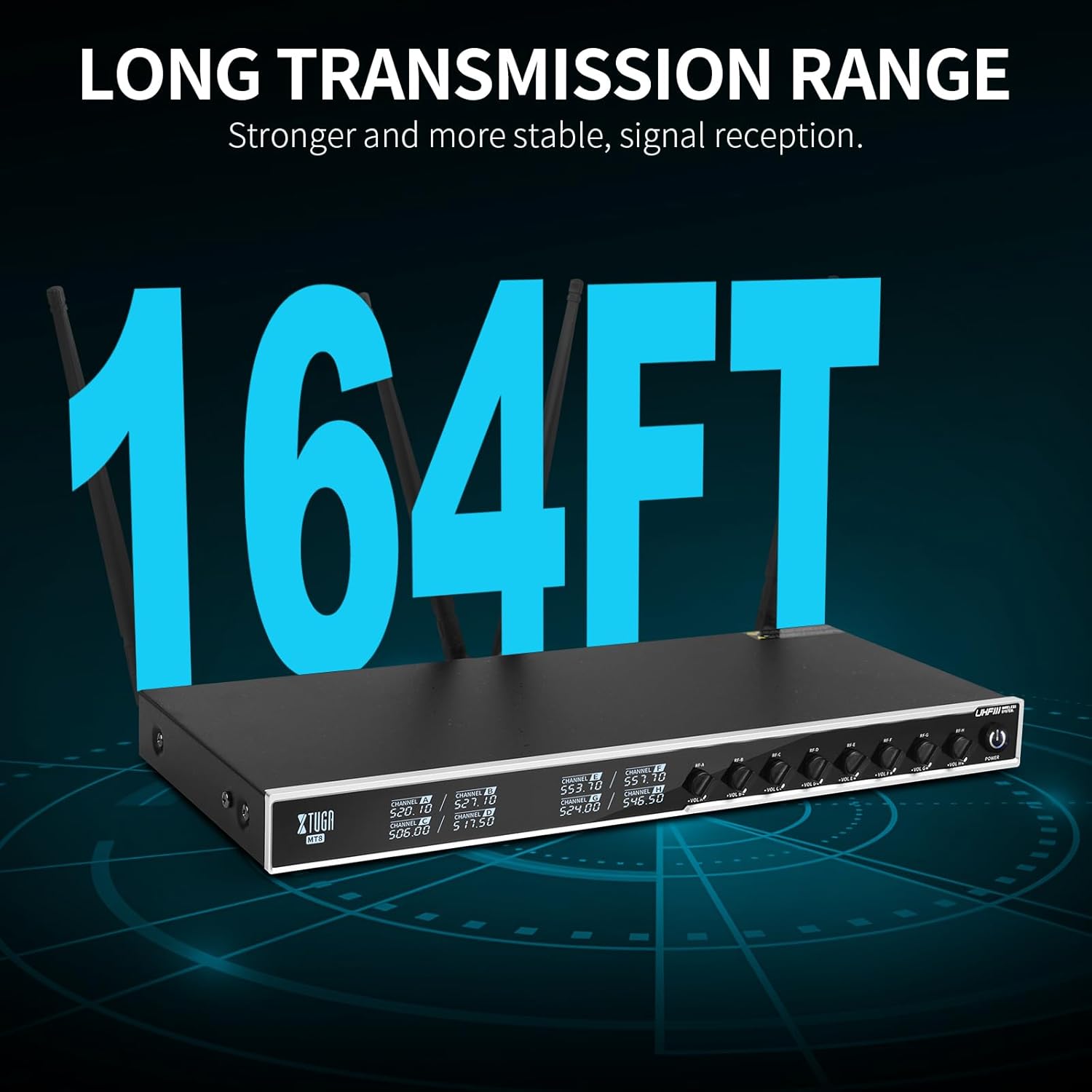
Image: Long Transmission Range. This image highlights the system's capability for a long and stable signal transmission range, up to 164 feet (50 meters) in optimal conditions.
The system offers a reliable line-of-sight operation range of up to 230ft (70m). For best performance, ensure a clear line of sight between the microphones and the receiver. Obstacles such as walls, metal structures, or large crowds can reduce the effective range.
Volume Control

Image: Volume Adjustment. This image demonstrates the independent volume adjustment feature on the receiver, allowing users to precisely control the audio level for each microphone.
Each microphone has an independent volume control knob on the receiver. Adjust these knobs to balance the audio levels of all active microphones. Monitor the audio output through your sound system to prevent clipping or distortion.
Suitable Applications

Image: Suitable Occasions. This image displays various events where the XTUGA MT8 system can be effectively used, including live performances, concerts, public speeches, and weddings.
- Live Performances
- Concerts
- Public Speaking and Conferences
- Weddings and Ceremonies
- Karaoke
- Church Services
- DJ Events
Maintenance
- Battery Replacement: Replace microphone batteries when the LED display indicates low power. Always use fresh, high-quality AA batteries. Remove batteries if the microphones will not be used for an extended period to prevent leakage.
- Cleaning:
- Wipe the receiver and microphone bodies with a soft, dry cloth.
- For microphone grilles, use a slightly damp cloth and ensure no moisture enters the microphone capsule.
- Do not use harsh chemicals, solvents, or abrasive cleaners.
- Storage: Store the system in a cool, dry place away from direct sunlight, extreme temperatures, and high humidity. Keep components in their original packaging or a protective case when not in use.
- Antenna Care: Handle antennas carefully to avoid bending or breaking. Ensure they are properly positioned for optimal signal.
Troubleshooting
| Problem | Possible Cause | Solution |
|---|---|---|
| No sound from microphone |
|
|
| Interference, static, or dropouts |
|
|
| Short transmission range |
|
|
Specifications
| Feature | Detail |
|---|---|
| Brand | XTUGA |
| Model Name | MT8 |
| Connectivity Technology | UHF, XLR |
| Connector Type | XLR |
| Special Feature | Volume Control |
| Compatible Devices | Amplifier, Audio Mixer, PA System |
| Polar Pattern | Unidirectional (Cardioid) |
| Item Weight | 4.85 Kilograms (System) |
| Microphone Form Factor | Handheld |
| Power Source | Battery Powered (Microphones) |
| Signal-to-Noise Ratio | 70 dB |
| Number of Channels | 8 |
| Audible Noise | 70 Decibels |
| Enclosure Material | Metal |
| Frequency Range | 540MHz-599.5MHz (15 selectable bands per channel) |
| Operating Range | Up to 230ft (70m) line-of-sight |
Warranty and Support
Warranty: The XTUGA MT8 Wireless Microphone System comes with a standard manufacturer's warranty. Please refer to the warranty card included in your package or visit the official XTUGA website for detailed warranty terms and conditions.
Customer Support: If you encounter any issues or have questions regarding your XTUGA MT8 system that are not covered in this manual, please contact XTUGA customer support. You can typically find contact information on the XTUGA website or through your purchase platform.
For more information, visit the official XTUGA Store on Amazon.


