
AZZUNO MIG-135F
AZZUNO MIG-135F Multiprocess Welder User Manual
Model: MIG-135F
Introduction
This manual provides essential information for the safe and effective operation, setup, and maintenance of your AZZUNO 135A Multiprocess Welder. This 3-in-1 machine supports Flux MIG, Lift TIG, and Stick welding processes, offering versatility for various welding tasks. Please read this manual thoroughly before operating the welder to ensure proper use and to prevent injury or damage.

Image: The AZZUNO 135A Multiprocess Welder, a compact unit with a blue and white casing, shown alongside two spools of .030" flux core welding wire.
Safety Information
Welding can be dangerous. Always follow safety precautions to prevent electric shock, burns, fire, and other serious injuries. This section outlines general safety guidelines. Refer to local safety standards and regulations for comprehensive information.
- Electric Shock: Ensure proper grounding. Do not touch live electrical parts. Wear dry welding gloves.
- Fumes and Gases: Work in a well-ventilated area. Use fume extractors if necessary.
- Arc Rays: Protect eyes and skin. Use a welding helmet with appropriate shade and protective clothing.
- Fire and Explosion: Keep flammable materials away from the welding area. Have a fire extinguisher readily available.
- Burns: Wear protective clothing, gloves, and footwear. Hot metal can cause severe burns.
- Overheating Protection: The machine is equipped with overload and overheating protection. Allow the machine to cool down if it triggers this protection.

Image: The AZZUNO 135A Multiprocess Welder in use, with overlaid icons highlighting its features: High Efficiency, IGBT Inverter technology, Overheating Protection, and suitability for Extensive Use.
Product Overview and Features
The AZZUNO MIG-135F is a versatile 3-in-1 welding machine designed for various applications. It features synergic control for simplified operation, automatically adjusting voltage and wire feed speed based on amperage or material thickness. This makes it suitable for both beginners and experienced welders.
Key Features:
- 3-in-1 Multiprocess: Supports Flux MIG, Lift TIG (torch not included), and Stick (MMA) welding.
- Synergic Control: Automatic adjustment of welding parameters for ease of use.
- Voltage Control Knob: For fine-tuning voltage.
- Wire Speed Adjustment Knob: For precise wire feed control.
- Overload and Overheating Protection: Enhances safety during operation.
- Compact and Portable: Designed for easy transport and storage.

Image: A visual representation of the three welding processes supported by the machine: Flux Cored Welding, Stick Welding, and Lift TIG Welding, each with an example of the process in action.

Image: The AZZUNO 135A Multiprocess Welder with examples of metal applications it is suitable for, including Iron Frame, Metal Shelf, Sheet Metal, and Mild Steel, demonstrating its versatility.
Setup
Before beginning any welding operation, ensure the machine is properly set up and all connections are secure.
Component Identification:

Image: A detailed diagram of the AZZUNO 135A MIG Welder's front panel, labeling key components such as Wire Feed Adjustment, Choose Button, Voltage Adjustment, Positive Terminal, Torch Output, Air Plug, and Negative Terminal.
- Wire Feed Adjustment: Controls the speed at which the welding wire is fed.
- Choose Button: Selects between welding modes (Flux MIG, Lift TIG, MMA).
- Voltage Adjustment: Controls the welding voltage.
- Positive Terminal: Connection point for the electrode holder (MMA) or MIG torch (MIG).
- Torch Output: Connection for the MIG torch.
- Air Plug: (If applicable, for gas-shielded MIG or TIG).
- Negative Terminal: Connection point for the ground clamp.
Installing Flux Core Wire:
The welder is designed to use .030" (0.8mm) and .035" (0.9mm) flux core wire for gasless MIG welding.
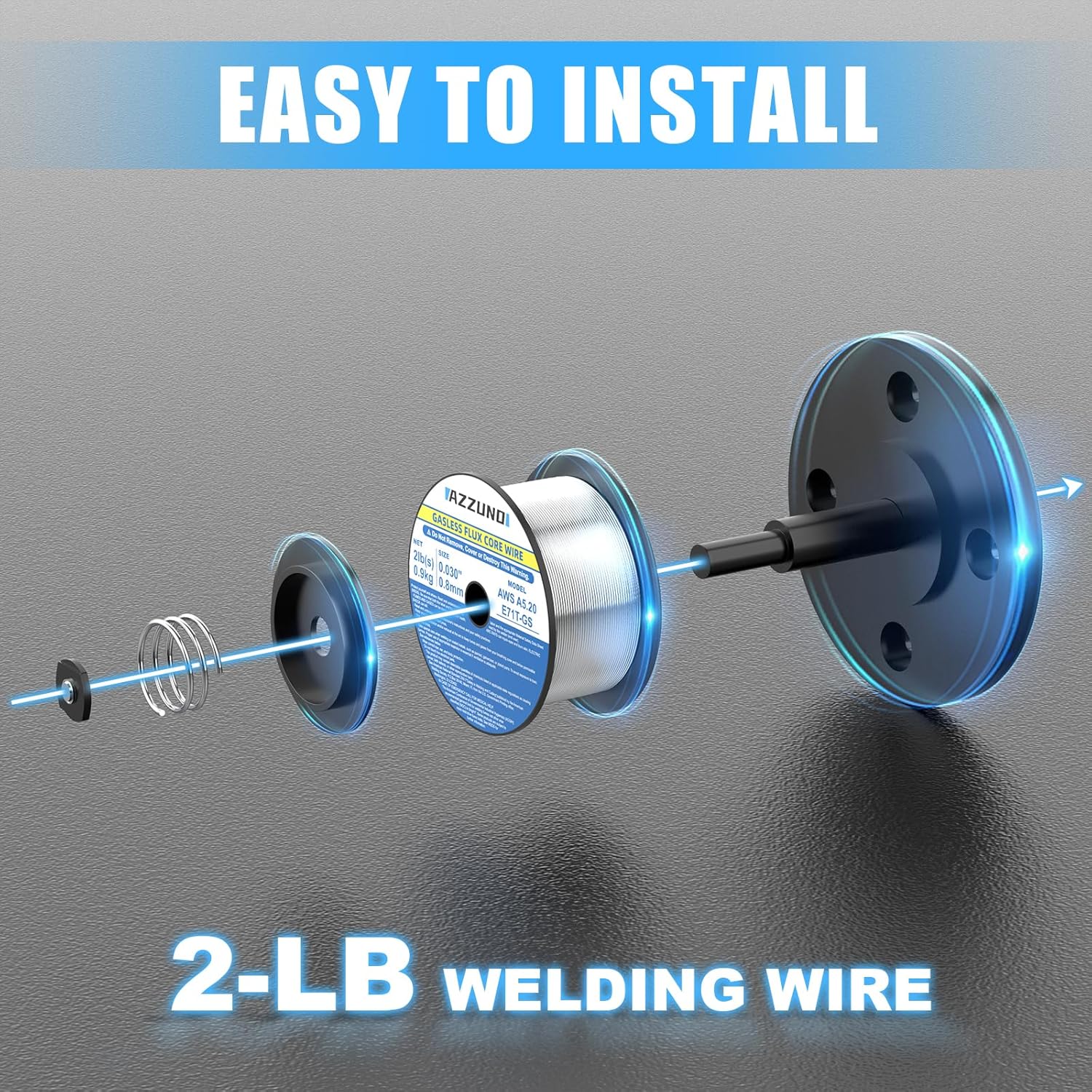
Image: An exploded view diagram illustrating the simple steps to install a 2-pound spool of welding wire into the welder's wire feeder mechanism.
- Open the wire feeder compartment.
- Place the flux core wire spool onto the spindle, ensuring it rotates freely.
- Thread the wire through the guide tube and into the drive rollers.
- Close the drive roller tension arm and adjust tension as needed (refer to the machine's internal diagram for specific tension settings).
- Feed the wire through the MIG torch liner until it exits the nozzle.
Connecting Accessories:

Image: The AZZUNO 135A MIG Welder displayed with its standard accessories: a ground clamp, an electrode holder, a MIG torch, a spool of flux cored wire, and a cleaning brush. The image also indicates the machine's dimensions and weight.
- Connect the ground clamp cable to the negative terminal. Attach the ground clamp securely to the workpiece.
- Connect the MIG torch cable to the torch output.
- For Stick (MMA) welding, connect the electrode holder cable to the positive terminal and the ground clamp to the negative terminal.
- For Lift TIG welding, connect the TIG torch (not included) to the appropriate terminal and the ground clamp to the negative terminal.
Operating Instructions
This section details the operation of the AZZUNO MIG-135F for its various welding modes.
General Operation Steps:
- Ensure all connections are correct and secure.
- Connect the welder to a suitable 110V power supply.
- Turn on the power switch.
- Use the "Choose" button to select the desired welding mode (Flux MIG, Lift TIG, or MMA).
- Adjust the amperage, voltage, and wire feed speed according to the material thickness and welding process. The synergic control will assist in setting optimal parameters.
- Perform a test weld on scrap material to verify settings.
Flux MIG Welding (Gasless):
- Select "Flux MIG" mode.
- Ensure .030" (0.8mm) or .035" (0.9mm) flux core wire is installed.
- Adjust voltage and wire feed speed. For synergic control, adjust amperage, and the machine will automatically set corresponding voltage and wire speed.
- Maintain a consistent stick-out and travel speed for optimal results.
- This mode is suitable for welding up to 5/32" (4.0mm) thick materials.
Lift TIG Welding:
- Select "Lift TIG" mode.
- Connect a Lift TIG torch (not included) and a gas cylinder if using shielding gas.
- Adjust amperage.
- Initiate the arc by gently touching the tungsten electrode to the workpiece and lifting slightly.
Stick (MMA) Welding:
- Select "MMA" mode.
- Connect the electrode holder to the positive terminal and the ground clamp to the negative terminal.
- Insert the appropriate electrode (e.g., E6013) into the holder.
- Adjust amperage based on the electrode type and diameter.
- Strike the arc by scratching or tapping the electrode on the workpiece.

Image: Demonstrations of various welding positions achievable with the welder, including Flat Welding, Vertical Welding, Up Welding, and Corner Welding, showcasing the versatility of the flux core wire.
Maintenance
Regular maintenance ensures the longevity and optimal performance of your welding machine.
- Cleaning: Regularly clean the machine's exterior with a dry cloth. Use compressed air to blow out dust from inside the machine, especially around the fan and circuit boards, ensuring the power is disconnected.
- Wire Feeder: Inspect the wire drive rollers for wear and cleanliness. Clean any debris or wire shavings.
- Torch and Cables: Check the MIG torch liner for blockages or wear. Inspect all cables for cuts, cracks, or damaged insulation. Replace damaged components immediately.
- Consumables: Replace worn contact tips, nozzles, and electrodes as needed.
- Storage: Store the welder in a dry, clean environment away from excessive dust and moisture.
Troubleshooting
This section provides solutions to common issues you might encounter.
| Problem | Possible Cause | Solution |
|---|---|---|
| No power to machine | Power cord unplugged, circuit breaker tripped, machine switch off | Check power connection, reset breaker, turn on machine switch |
| No arc | Poor ground connection, wrong mode selected, worn contact tip, incorrect settings | Ensure good ground, select correct mode, replace tip, adjust settings |
| Wire not feeding | Wire tangled, drive rollers dirty/worn, tension too low/high, liner blocked | Untangle wire, clean/replace rollers, adjust tension, clear liner |
| Machine overheats (protection triggered) | Exceeded duty cycle, poor ventilation, fan blocked | Allow machine to cool, ensure proper airflow, clear fan vents |
If problems persist after attempting these solutions, please contact AZZUNO customer support.
Specifications
Technical specifications for the AZZUNO 135A Multiprocess Welder and included flux core wire.
| Feature | Detail |
|---|---|
| Model | MIG-135F |
| Input Voltage | 110V |
| Welding Processes | Flux MIG, Lift TIG, Stick (MMA) |
| MIG Wire Compatibility | .030" (0.8mm), .035" (0.9mm) Flux Core Wire |
| Max Welding Thickness (Flux MIG) | Up to 5/32" (4.0mm) |
| ARC Mode Rods | E6013 |
| Control Type | Synergic Control |
| Protection | Overload, Overheating |
Flux Core Welding Wire Specifications:
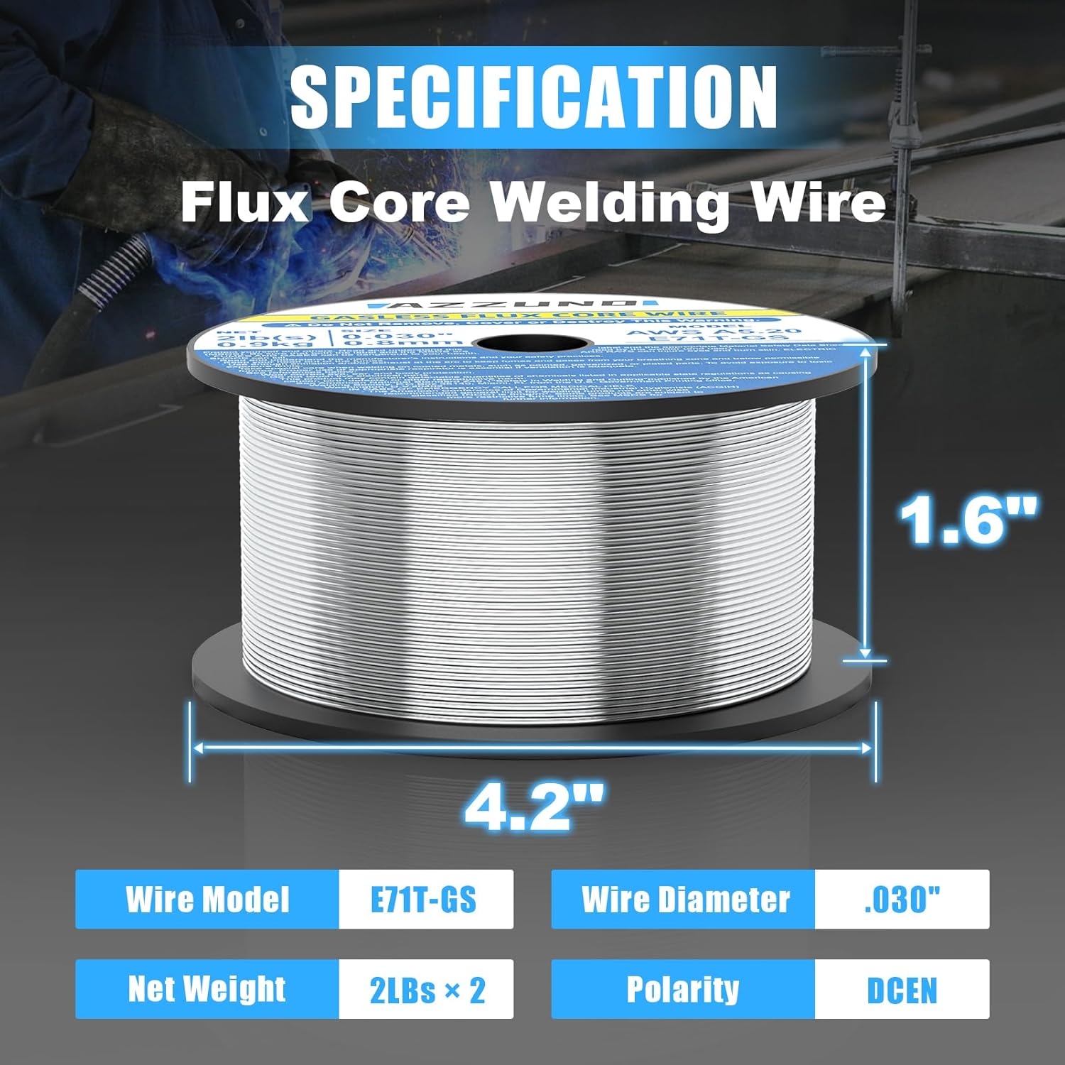
Image: A spool of AZZUNO Flux Core Welding Wire with its specifications clearly labeled: Wire Model E71T-GS, Wire Diameter .030", Net Weight 2LBS x 2, and Polarity DCEN.
| Feature | Detail |
|---|---|
| Wire Model | AWS E71T-GS |
| Wire Diameter | .030" (0.8mm) |
| Net Weight | 2 LBS per spool (2-pack included) |
| Polarity | DCEN (Direct Current Electrode Negative) |
Warranty and Support
For warranty information, product registration, or technical support, please refer to the official AZZUNO website or contact their customer service directly. Keep your purchase receipt as proof of purchase for warranty claims.
Note on Videos: No official product videos from the seller were found in the provided data for this product. Please refer to the manufacturer's website or authorized channels for any available video resources.
Contact Information:
- Brand: AZZUNO
- Website: Visit the AZZUNO Store on Amazon
- For specific support, refer to the contact details provided with your product packaging or on the official AZZUNO website.
Related documentsMIG-135F


Ask a question about this manual
Ask about setup, troubleshooting, compatibility, parts, safety, or missing instructions. Manuals+ will review the question and use this page’s manual context to help answer it.