
Aoleaby METSEPM5500
Aoleaby METSEPM5500 PM5500 Series Power Meter User Manual
Model: METSEPM5500
1. Introduction
This manual provides comprehensive instructions for the installation, operation, maintenance, and troubleshooting of the Aoleaby METSEPM5500 PM5500 Series Power Meter. This device is designed for precise power and energy monitoring, featuring RS485 communication for remote data acquisition.
2. Safety Information
WARNING: Electrical shock hazard. Installation and servicing should only be performed by qualified personnel.
- Always disconnect power before installing or servicing the device.
- Ensure all wiring complies with local and national electrical codes.
- Do not operate the device in environments exceeding its specified operating temperature or humidity ranges.
- Use appropriate personal protective equipment (PPE) when working with electrical systems.
3. Product Overview
The Aoleaby METSEPM5500 PM5500 Series Power Meter is a feature-rich device for advanced power and energy measurement. Key features include:
- Feature-rich power and energy metering capabilities.
- Digital input and output for monitoring and control relays.
- Modbus RS485 communication port for remote monitoring and integration.
- High precision accuracy of Class 0.2S for active power, compliant with IEC 62053-22.
- Harmonic measurement for comprehensive power quality management.
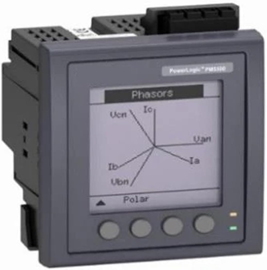
Figure 3.1: Front view of the Aoleaby METSEPM5500 Power Meter displaying a phasor diagram.

Figure 3.2: Front view of the Aoleaby METSEPM5500 Power Meter, highlighting the LCD display and control buttons.
4. Setup and Installation
4.1 Unpacking and Inspection
Carefully unpack the power meter and inspect it for any signs of damage. Ensure all components are present as per the packing list.
4.2 Mounting
The device is designed for panel mounting. Refer to the dimensions provided in the specifications section for appropriate panel cutout requirements. Secure the meter using the provided mounting clips or screws.
4.3 Wiring Connections
Connect the power supply, voltage inputs, current transformer (CT) inputs, and RS485 communication lines according to the wiring diagrams provided in the full product documentation (not included in this manual). Ensure correct polarity and secure connections for all terminals.
- Power Supply: Connect the supply voltage (125-250 V DC or 100-480 V AC, 45-65 Hz) to the designated terminals.
- Current Inputs: Connect current transformers (CTs) to the 1A or 5A rated current inputs.
- Voltage Inputs: Connect the voltage inputs (e.g., 110V, 230V) to the appropriate terminals.
- RS485 Communication: Connect the RS485 A and B lines to your communication network.
- Digital I/O: Connect external devices to the digital input and output terminals as required for monitoring or control.
5. Operating Instructions
5.1 Powering On
Once all connections are secure, apply power to the device. The LCD backlight display will illuminate, and the meter will initiate its startup sequence.
5.2 Display Navigation
The PM5500 features an LCD backlight display with 128 x 128 resolution and control buttons on the front panel. Use these buttons to navigate through various measurement screens, settings, and menus. Specific button functions (e.g., UP, DOWN, ENTER, ESC) are detailed in the full product manual.
5.3 Reading Measurements
The meter displays real-time measurements for various electrical parameters, including:
- Voltage (V)
- Current (A)
- Active Power (W)
- Reactive Power (VAR)
- Apparent Power (VA)
- Power Factor (PF)
- Frequency (Hz)
- Energy (kWh, kVARh)
- Harmonics
Navigate through the display screens to view the desired parameters. The meter's internal memory stores energy readings up to 999999 units.
5.4 RS485 Communication
The Modbus RS485 communication port allows for remote data acquisition and control. Configure the communication parameters (e.g., baud rate, parity, slave ID) via the meter's menu system to match your Modbus network settings. Refer to the Modbus communication protocol guide in the full product manual for detailed register maps and commands.
6. Maintenance
6.1 Cleaning
Keep the meter clean by wiping the display and casing with a soft, dry cloth. Do not use abrasive cleaners or solvents, as these may damage the display or housing.
6.2 Environmental Conditions
Ensure the operating environment remains within the specified temperature range of -10°C to +50°C and appropriate humidity levels to ensure optimal performance and longevity of the device.
7. Troubleshooting
7.1 No Display/No Power
- Check the power supply connections and ensure the correct voltage is applied.
- Verify that the circuit breaker or fuse supplying power to the meter is not tripped or blown.
7.2 Incorrect Readings
- Confirm that voltage and current transformer (CT) connections are correct and securely fastened.
- Ensure the CT ratios are correctly configured in the meter's settings.
- Verify the phase configuration (single phase) matches the installation.
7.3 RS485 Communication Errors
- Check the RS485 wiring for correct polarity (A to A, B to B) and secure connections.
- Verify that the communication parameters (baud rate, parity, stop bits, slave ID) in the meter match those of the master device.
- Ensure proper termination resistors are used on the RS485 bus if required.
For further troubleshooting or issues not covered here, please refer to the full product manual or contact technical support.
8. Specifications
| Parameter | Value |
|---|---|
| Model Number | METSEPM5500 (PM5500 Series) |
| Display Type | LCD backlight display, 128 x 128 resolution |
| Phase | Single Phase |
| Measuring Energy Range | 0-999999 |
| Accuracy Class (Active Power) | 0.2S (complies with IEC 62053-22) |
| Output Voltage (Supported) | 110V, 127V, 133V, 230V, 240V |
| Operating Temperature | -10°C to +50°C |
| Dimensions | 117.5 x 58.5 x 18 mm (approximate) |
| Net Weight | 450 g (approx. 1.1 pounds) |
| Supply Voltage | 125-250 V DC, 100-480 V AC (45-65 Hz) |
| Rated Current Input | 1 A, 5 A |
| Communication | Modbus RS485 |
9. Warranty and Support
For information regarding product warranty, technical support, or service, please refer to the documentation provided with your purchase or contact the manufacturer, Aoleaby, directly. Contact details can typically be found on the manufacturer's official website or through your point of purchase.
Ask a question about this manual
Ask about setup, troubleshooting, compatibility, parts, safety, or missing instructions. Manuals+ will review the question and use this page’s manual context to help answer it.