1. Introduction
This manual provides detailed instructions for the Wishiot HX711 Load Cell Amplifier Module. The HX711 is a 24-bit high-precision analog-to-digital converter (ADC) chip designed for electronic weighing scales and pressure sensors. It features two analog input channels and an internal programmable gain amplifier, making it suitable for bridge-type sensor applications. This module offers high precision and low cost, making it an ideal front-end module for various sensing applications.
The HX711 module is commonly used with load cells for applications such as weighing scales, kitchen scales, and industrial process control. It supports various load cell capacities, including 1kg, 2kg, 3kg, 5kg, 10kg, 20kg, and 50kg.

Figure 1: Ten HX711 Load Cell Amplifier Modules. Each module is a small green PCB with the HX711 chip and associated components, accompanied by pin headers for connection.
2. Features
- High Precision: Utilizes a 24-bit high-precision A/D converter chip (HX711).
- Input Channels: Two selectable differential input channels.
- Programmable Gain Amplifier (PGA): On-chip active low-noise PGA with selectable gains of 32, 64, and 128.
- Power Supply Regulator: On-chip power supply regulator for load-cell and ADC analog power supply.
- Oscillator: On-chip oscillator requiring no external components, with an option for an external crystal.
- Power-on-Reset: Integrated power-on-reset function.
- Simple Interface: Simple digital control and serial interface; pin-driven controls, no programming needed for basic operation.
- Noise Rejection: Simultaneous 50Hz and 60Hz supply rejection.
- Low Power Consumption: Normal operation <1.5mA, power down <1uA (including on-chip analog power supply regulator).
- Wide Operating Voltage: 2.6V to 5.5V.
- Temperature Range: -20°C to +85°C.
3. Setup and Wiring
Proper connection of the HX711 module to a load cell and a microcontroller (e.g., Arduino) is crucial for accurate measurements. Follow the diagrams and instructions below.
3.1 Module Dimensions
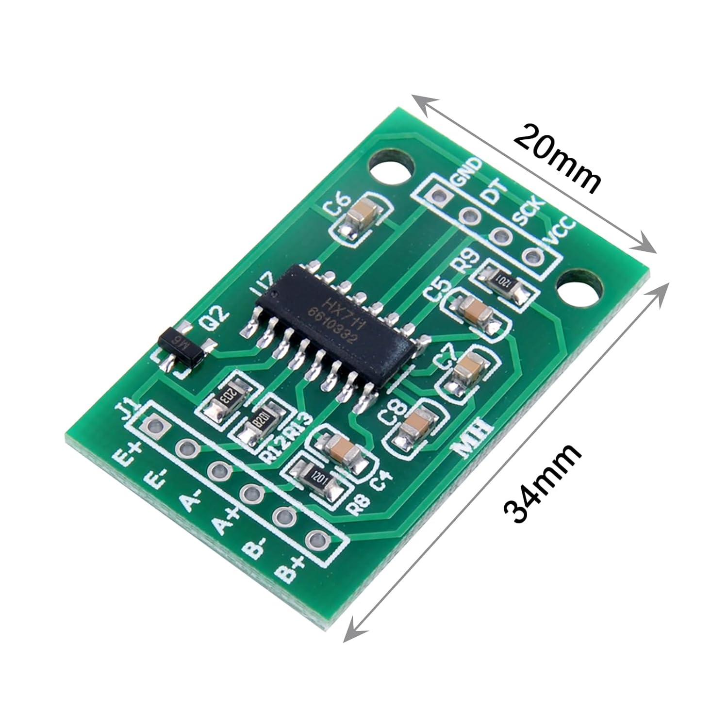
Figure 2: HX711 Module Dimensions. The module measures approximately 34mm in length and 20mm in width, with mounting holes at each corner.

Figure 3: Back view of the HX711 Module. This image shows the underside of the PCB, revealing solder pads for connections.
3.2 Load Cell Wiring
Load cells typically use a Wheatstone bridge configuration. The HX711 module is designed to interface directly with these bridge-type sensors.

Figure 4: Load Cell Wiring Diagram. This diagram illustrates the Wheatstone bridge configuration of a load cell and its connection points (E+, E-, A+, A-, B+, B-) to the HX711 module. The HX711 also shows connections for GND, DT (Data Out), SCK (Clock In), and VCC (3.3V/5V Supply).
- E+ (Excitation+): Connect to the positive excitation voltage of the load cell.
- E- (Excitation-): Connect to the negative excitation voltage of the load cell.
- A+ (Output+): Connect to the positive output signal of the load cell (Channel A).
- A- (Output-): Connect to the negative output signal of the load cell (Channel A).
- B+ (Output+): Connect to the positive output signal of the load cell (Channel B, if used).
- B- (Output-): Connect to the negative output signal of the load cell (Channel B, if used).
Note: It is recommended to use channel A for small signal input from the sensor. Channel B can be used for system parameter detection, such as battery voltage.
3.3 HX711 to Microcontroller Wiring (e.g., Arduino)
The HX711 communicates with a microcontroller via a simple 2-wire serial interface (Data and Clock).
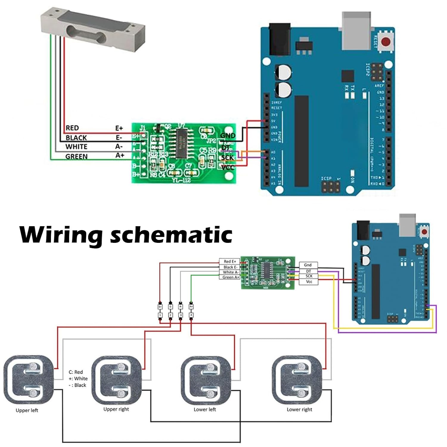
Figure 5: HX711 to Arduino Wiring Schematic. This diagram shows a typical connection of the HX711 module to an Arduino board. The load cell connects to the E and A pins of the HX711. The HX711's VCC connects to Arduino's 5V, GND to GND, DT to a digital pin (e.g., A1), and SCK to another digital pin (e.g., A0).
- VCC: Connect to 2.6V - 5.5V power supply (e.g., 5V from Arduino).
- GND: Connect to ground.
- DT (Data Output): Connect to a digital input pin on your microcontroller.
- SCK (Clock Input): Connect to a digital output pin on your microcontroller.
Ensure all digital input pins (RATE, XI, PD_SCK) are properly connected and not left floating. Refer to the HX711 datasheet for detailed pin functions.
4. Operating Principles
The HX711 is a precision 24-bit analog-to-digital converter designed for weigh scales and industrial control applications to interface directly with a bridge sensor. It integrates a programmable gain amplifier (PGA) with selectable gains of 32, 64, and 128. The output data rate can be set to 10SPS (samples per second) or 80SPS.

Figure 6: HX711 Internal Block Diagram and Circuit. This image displays the internal architecture of the HX711 chip, including the input MUX, PGA, 24-bit ADC, internal oscillator, and digital interface. A detailed circuit diagram shows external component connections for power supply and sensor interface.
To operate the module, a microcontroller sends clock pulses to the SCK pin. After a certain number of clock pulses, the HX711 will output the converted digital data on the DT pin. The number of clock pulses determines the gain setting and channel selection.
- Channel A: Can be set for a programmable gain of 128 or 64.
- Channel B: Has a fixed gain of 32.
Most applications will use Channel A with a gain of 128 for maximum sensitivity when reading load cells.
5. Maintenance and Cautions
To ensure the longevity and accurate performance of your HX711 module, observe the following cautions:
- Digital Input Pins: All digital input pins, including RATE, XI, and PD_SCK, do not have built-in pull-up or pull-down resistors. These pins must not be left floating (dangling) when in use. Ensure they are properly connected to a defined logic level.
- Power Supply Stability: Whether using the on-chip regulated power supply or an external system power supply, it is crucial that the power supply to the sensor and the A/D converter is stable. Instability can lead to inaccurate readings.
- Analog Power Supply: It is recommended that the sensor and the A/D converter use the same analog power supply for optimal performance and noise reduction.
- PNP Tube S8550: If using the on-chip voltage regulator power supply circuit, it is recommended to use a PNP tube S8550. Other MOS or bipolar transistors can be used, but attention should be paid to the stability of the regulated power supply.
- Clock Pulses: The number of input clock pulses should not be less than the required amount for data retrieval and gain setting. Refer to the HX711 datasheet for specific timing requirements.
6. Troubleshooting
If you encounter issues with your HX711 module, consider the following troubleshooting steps:
- No Readings or Erratic Data:
- Verify all wiring connections, especially VCC, GND, DT, and SCK, as well as the load cell connections (E+, E-, A+, A-).
- Ensure no digital input pins are left floating.
- Check the power supply voltage to the HX711 module; it should be within 2.6V to 5.5V.
- Confirm the load cell is correctly wired as a Wheatstone bridge.
- Review your microcontroller code for correct timing and data reading sequence for the HX711.
- Inaccurate Readings:
- Calibrate your load cell and HX711 setup. This typically involves reading known weights and calculating a calibration factor.
- Ensure the power supply is stable and free from noise.
- Check for any physical interference or strain on the load cell that might affect readings.
- Verify the gain setting in your code matches the desired sensitivity (e.g., 128 for most load cells).
- Module Not Responding:
- Check power connections (VCC, GND).
- Ensure the SCK pin is receiving clock pulses from the microcontroller.
- Verify the microcontroller's digital pins are correctly configured as input/output for DT/SCK.
7. Specifications
| Specification | Value |
|---|---|
| ADC Resolution | 24-bit |
| Input Channels | 2 differential (Channel A, Channel B) |
| Programmable Gain | Channel A: 128 or 64; Channel B: 32 |
| Operating Voltage Range | 2.6V ~ 5.5V |
| Operating Temperature Range | -20°C ~ +85°C |
| Current Consumption (Normal) | <1.5mA |
| Current Consumption (Power Down) | <1uA |
| Simultaneous Noise Rejection | 50Hz and 60Hz |
| Product Dimensions | 1.34 x 0.08 x 0.79 inches (approx. 34 x 2 x 20 mm) |
| Item Model Number | WS0728X10 |
| Manufacturer | Wishiot |
8. Support
For further assistance, detailed tutorials, or specific technical inquiries regarding the Wishiot HX711 Load Cell Amplifier Module, please contact Wishiot customer service. They can provide additional resources and support for your application needs.
You can typically find contact information on the product's purchase page or the official Wishiot store page.