1. Introduction
This manual provides essential instructions for the installation, operation, and maintenance of the Walfront CHLT-616 3 Phase Adjustable Voltage Protector. This device is engineered to safeguard electrical equipment from various power anomalies, including over-voltage, under-voltage, voltage imbalance, phase fault, phase failure, and overcurrent conditions. It features an automatic reset function to restore power after a fault clears and a real-time LED display for continuous monitoring of voltage parameters.
The CHLT-616 is designed for standard 35mm DIN rail mounting, ensuring convenient and sturdy installation within electrical panels. Its sensitive internal components and quick response speed contribute to reliable protection for your connected systems.
2. Safety Information
Please read and understand all safety warnings and instructions before installing or operating this device. Failure to do so may result in electric shock, fire, or serious injury.
- Qualified Personnel Only: Installation and maintenance should only be performed by qualified electricians or personnel with appropriate electrical training.
- Disconnect Power: Always disconnect the main power supply before performing any wiring, installation, or maintenance on the device.
- Proper Wiring: Ensure all wiring connections are secure and comply with local electrical codes and the provided wiring diagram. Incorrect wiring can lead to device malfunction or hazards.
- Environmental Conditions: Do not expose the device to moisture, extreme temperatures outside its specified operating range, or corrosive environments.
- Ventilation: Ensure adequate ventilation around the device to prevent overheating.
- Intended Use: Use the device only for its intended purpose as a voltage protector. Do not attempt to modify or disassemble the unit.
3. Product Overview
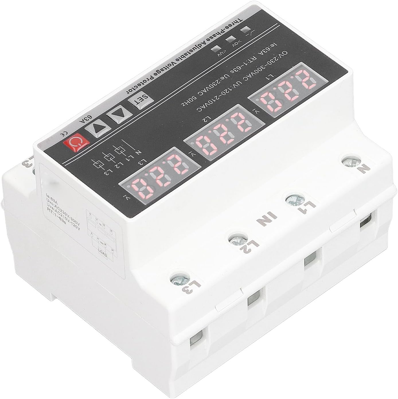
The Walfront CHLT-616 is a compact and robust 3-phase voltage protector featuring a clear LED display and user-friendly controls.
3.1 Components
- LED Digital Panels: Three separate digital displays show the real-time voltage for each phase (L1, L2, L3).
- Control Buttons: 'SET' button for entering settings mode, 'Up' and 'Down' arrows for adjusting parameters, and a power button.
- Input Terminals (IN): Connections for the incoming 3-phase power supply (N, L1, L2, L3).
- Output Terminals (OUT): Connections for the protected load (N, L1, L2, L3).
- DIN Rail Mounting Clip: Located on the bottom for secure installation on a 35mm DIN rail.
3.2 Product Views


4. Specifications
| Parameter | Value |
|---|---|
| Model | CHLT-616 |
| Rated Power Supply Voltage | AC230V |
| Working Voltage Range | AC120V-300V |
| Rated Frequency | 50/60Hz |
| Overvoltage Detection Value | 230-300V (factory set 270V) |
| Undervoltage Value | 120V-210V (factory set 170V) |
| Recovery Delay | 1-600s (factory set 30s) |
| Overcurrent Value | 1-63A (factory set 63A) |
| 3 Phase Voltage Imbalance Recovery Value | 5V-95V (factory set 10V) |
| Phase Sequence Switch | ON/OFF (factory set ON) |
| Display Type | LED |
| Voltage Measurement Accuracy | ≤1% (within the entire range) |
| Rated Insulation Voltage | 450V |
| Protection Level | IP20 |
| Pollution Level | 3 |
| Working Temperature | -5℃ to 40℃ |
| Humidity | ≤50% at 40℃ (non-condensing) |
| Storage Temperature | -25℃ to 55℃ |
| Installation | 35mm DIN Rail |
| Item Weight | 10.9 ounces |
| Package Dimensions | 3.94 x 3.54 x 3.15 inches |
5. Setup and Installation
Proper installation is crucial for the safe and effective operation of the voltage protector. Refer to the wiring diagram provided with your product packaging for precise connection details.
5.1 DIN Rail Mounting
- Ensure the main power supply is disconnected at the circuit breaker before beginning installation.
- Locate a suitable 35mm DIN rail within your electrical panel.
- Align the DIN rail mounting clip on the back of the protector with the DIN rail.
- Press the protector firmly onto the DIN rail until it clicks securely into place.
5.2 Wiring Connections
The device has clearly labeled input ('IN') and output ('OUT') terminals for Neutral (N) and three phases (L1, L2, L3).
- Input Wiring: Connect the incoming 3-phase power supply to the 'IN' terminals. Ensure that Neutral (N), Phase 1 (L1), Phase 2 (L2), and Phase 3 (L3) are connected to their corresponding terminals on the protector.
- Output Wiring: Connect the protected load to the 'OUT' terminals. Ensure that Neutral (N), Phase 1 (L1), Phase 2 (L2), and Phase 3 (L3) from the protector's output are connected to the corresponding terminals of your equipment.
- Secure Connections: Tighten all terminal screws firmly to prevent loose connections, which can cause overheating or intermittent operation.
- Verify Wiring: Double-check all connections against the product's wiring diagram before restoring power.
6. Operating Instructions
Once installed and wired correctly, the Walfront CHLT-616 operates largely automatically. However, understanding its display and adjustment features is important.
6.1 Power On/Off
After restoring power to the circuit, the device will power on. The LED displays will illuminate, showing the current voltage for each phase. The red power button can be used for manual power cycling if needed.
6.2 LED Display
The three digital panels continuously display the real-time voltage of L1, L2, and L3. This allows for immediate visual confirmation of the power supply status.
6.3 Parameter Adjustment
The device allows for adjustment of various protection parameters. Refer to the detailed instructions provided with the product for specific steps on how to enter the settings mode using the 'SET' button and modify values with the 'Up' and 'Down' arrows. Parameters typically include:
- Overvoltage (OV) threshold
- Undervoltage (UV) threshold
- Recovery Delay time
- Overcurrent (OC) value
- Voltage Imbalance recovery value
- Phase Sequence switch (ON/OFF)
Note: Adjusting these parameters should only be done by qualified personnel who understand the implications of changing protection settings.
6.4 Automatic Reset Function
The protector is equipped with an automatic reset function. If a voltage anomaly (over-voltage, under-voltage, etc.) occurs and the device trips, it will automatically attempt to restore power to the load after the fault condition has cleared and the set recovery delay time has elapsed. This prevents prolonged power outages due to transient issues.
7. Maintenance
The Walfront CHLT-616 is designed for minimal maintenance. However, periodic checks can help ensure its continued reliability.
- Visual Inspection: Periodically inspect the device for any signs of physical damage, discoloration, or loose connections.
- Cleaning: If necessary, gently clean the exterior of the device with a dry, soft cloth. Do not use abrasive cleaners or solvents. Ensure power is disconnected before cleaning.
- Functionality Check: If possible and safe to do so, periodically test the protection functions by simulating fault conditions (e.g., using a variable voltage source) to ensure the device trips and recovers as expected. This should only be done by qualified personnel.
8. Troubleshooting
If the voltage protector is not functioning as expected, consider the following troubleshooting steps:
- No Power/Display Off:
- Check the main power supply to the circuit.
- Verify all input wiring connections are secure.
- Ensure the device's power button is in the ON position.
- Device Trips Frequently:
- Check the incoming voltage for actual over-voltage or under-voltage conditions using a multimeter.
- Verify the load current does not exceed the set overcurrent value.
- Inspect for voltage imbalance or phase loss in the supply.
- Review the set protection parameters (OV, UV, OC thresholds) to ensure they are appropriate for your application.
- Device Does Not Reset:
- Ensure the fault condition (e.g., over-voltage) has genuinely cleared.
- Check the 'Recovery Delay' setting; the device will wait for this period before attempting to reset.
- If the fault persists, the device will not reset until the condition is resolved.
- Incorrect Voltage Reading:
- Compare the display reading with a calibrated multimeter. If there's a significant discrepancy, the device may require service.
If problems persist after following these steps, contact Walfront customer support or a qualified electrician.
9. Warranty and Support
Walfront products are manufactured to high-quality standards and are typically covered by a limited warranty against defects in materials and workmanship. Please refer to the warranty card included with your purchase or visit the official Walfront website for detailed warranty terms and conditions.
For technical support, troubleshooting assistance, or warranty claims, please contact Walfront customer service through the retailer where the product was purchased or via the contact information provided on the Walfront official website.


