
1. Introduction
This manual provides detailed instructions for the installation, operation, and maintenance of your GAMEON Emperor Artic Series Mid Tower PC Gaming Case. Please read this manual thoroughly before beginning assembly to ensure proper setup and safe usage. Retain this manual for future reference.

Image 1: Front-left view of the GAMEON Emperor Artic Series PC Gaming Case, showcasing its tempered glass panels and illuminated internal components.
2. Safety Information
- Always disconnect the power supply from the wall outlet before installing or servicing any components inside the PC case.
- Handle tempered glass panels with care. They are fragile and can break if dropped or subjected to impact.
- Wear anti-static gloves or use an anti-static wrist strap when handling internal components to prevent electrostatic discharge (ESD) damage.
- Keep small parts and accessories out of reach of children.
- Ensure proper ventilation around the PC case to prevent overheating.
3. Package Contents
Verify that all items are present in the package:
- GAMEON Emperor Artic Series Mid Tower PC Gaming Case
- Pre-installed 7 x 120mm ARGB+PWM Fans
- Accessory Kit (screws, standoffs, cable ties, etc.)
- User Manual (this document)
4. Product Features
The GAMEON Emperor Artic Series PC Gaming Case is designed for optimal performance and aesthetics:
- Tempered Glass Panels: Features 0.7mm tempered glass panels on the front and side for a clear view of internal components.
- Advanced Cooling: Comes with 7 pre-installed 120mm ARGB+PWM fans for efficient airflow and customizable lighting. Supports extensive fan and radiator configurations.
- Motherboard Compatibility: Supports ATX and M-ATX motherboard form factors.
- Spacious Interior: Accommodates GPUs up to 410mm in length and CPU coolers up to 165mm in height.
- Flexible Storage Options: Supports up to 2 HDDs and 1 SSD, or 1 HDD and 2 SSDs.
- Convenient I/O Ports: Includes 1x USB 3.0, 1x USB 2.0, 1x Type-C, HD Audio, and Reset/Power buttons.
- Durable Construction: Made from high-quality SPCC materials.
- Dust Filters: Equipped with dust filters for improved system longevity and reduced maintenance.

Image 2: Illustration of ARGB+PWM fan capabilities and the included remote control for lighting and fan speed adjustments.

Image 3: Detailed view of the accessible I/O ports located on the top panel of the case.
5. Setup Guide
5.1. Preparing the Case
- Place the case on a flat, stable surface.
- Carefully remove the side tempered glass panel by unscrewing the thumb screws (if present) or releasing the latch mechanism. Set the panel aside on a soft, non-abrasive surface to prevent scratches.
- Remove the front tempered glass panel if necessary for installation or access.
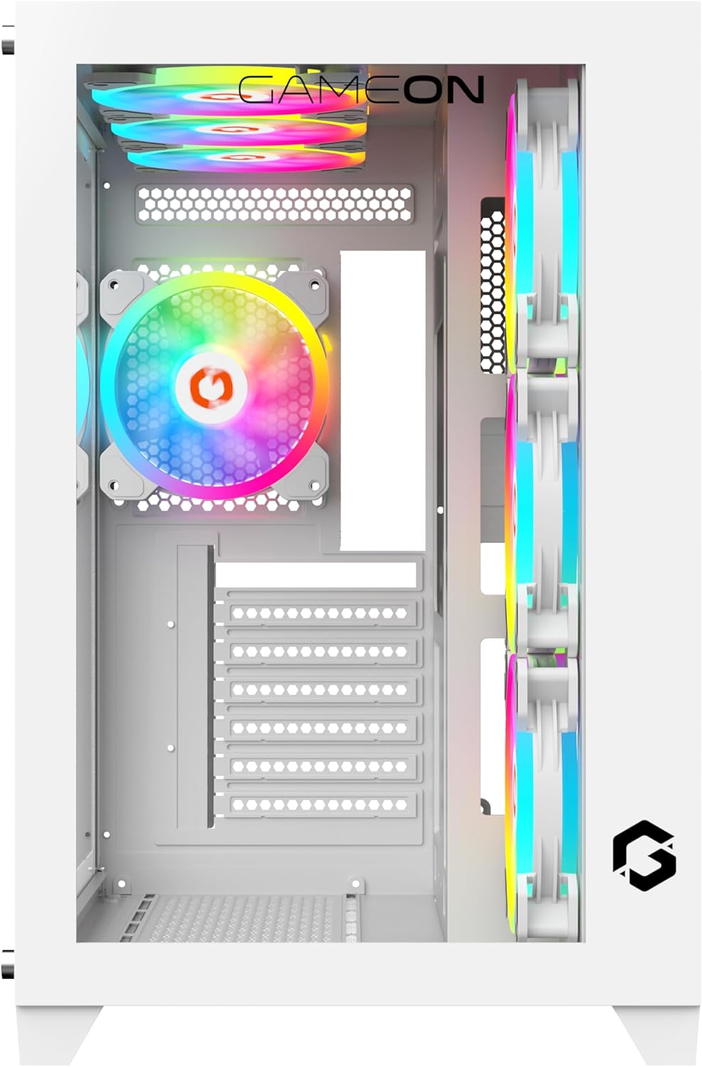
Image 4: Internal view of the case, illustrating the layout for component installation.
5.2. Motherboard Installation
- Install the I/O shield into the motherboard tray opening from the inside of the case.
- Align your ATX or M-ATX motherboard with the pre-installed standoffs. Ensure the screw holes on the motherboard match the standoffs.
- Secure the motherboard with the provided screws from the accessory kit.
5.3. Power Supply Unit (PSU) Installation
- Locate the PSU mounting area, typically at the bottom rear of the case.
- Slide your PSU (maximum length 200mm) into the designated bay.
- Secure the PSU with screws from the outside rear of the case.
5.4. Storage Drive Installation (HDD/SSD)
The case supports up to 2 HDDs and 1 SSD, or 1 HDD and 2 SSDs.
- Identify the drive bays or mounting brackets for 3.5" HDDs and 2.5" SSDs.
- Mount your drives using the appropriate screws. Some bays may feature tool-less designs.
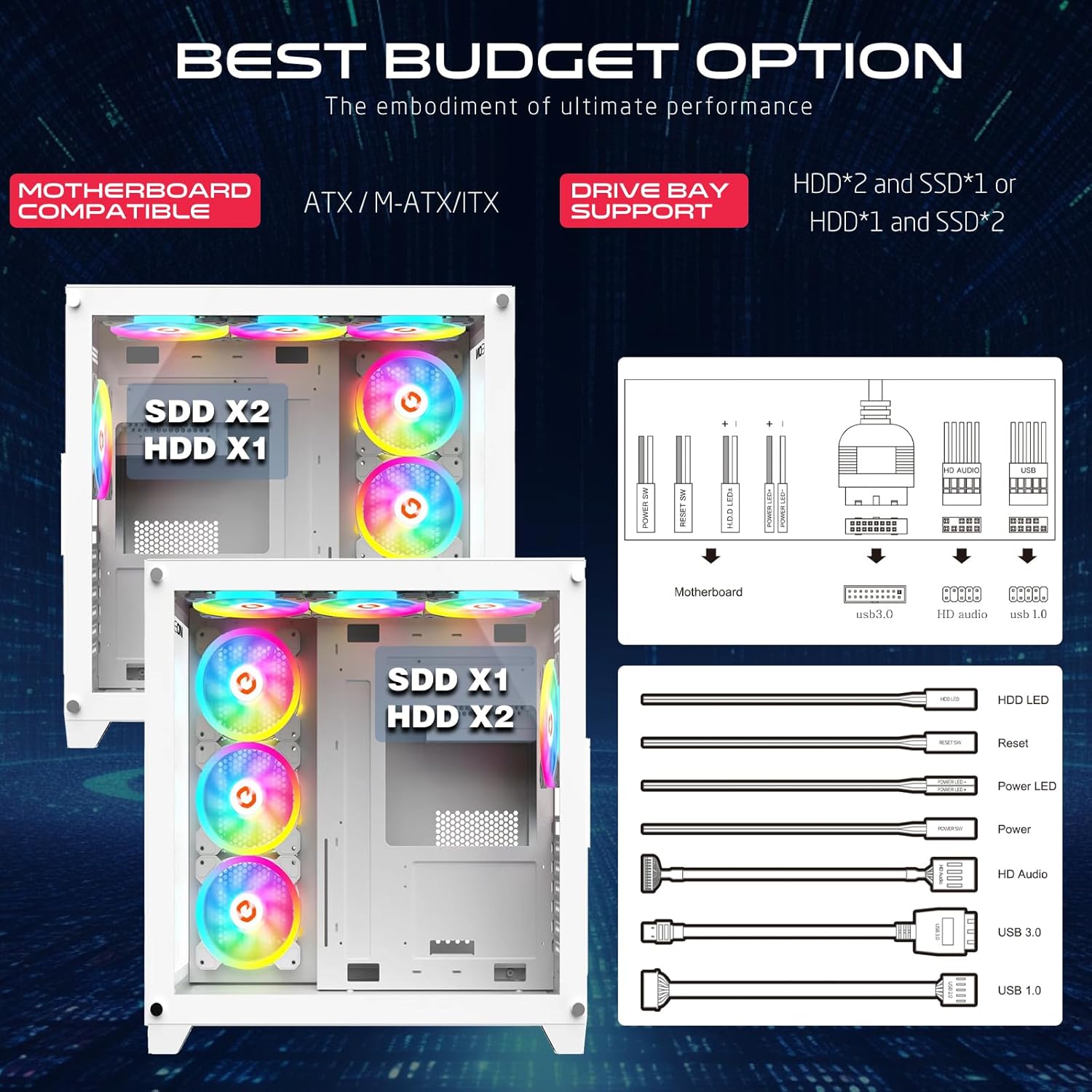
Image 5: Drive bay support configurations and front panel connector details.
5.5. Graphics Card (GPU) Installation
- Remove the necessary expansion slot covers at the rear of the case.
- Insert your GPU (maximum length 410mm) into the PCIe slot on the motherboard.
- Secure the GPU with screws.
5.6. Cable Management
Utilize the cable routing cutouts and tie-down points behind the motherboard tray to organize cables. This improves airflow and aesthetics.
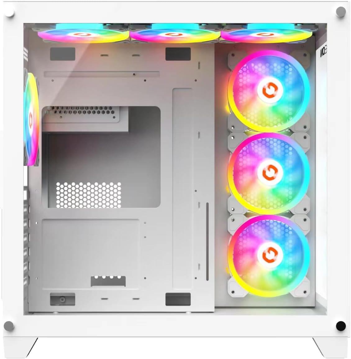
Image 6: Rear internal view, highlighting cable management options.
5.7. Connecting I/O Panel Cables
Connect the front panel cables (USB 3.0, USB 2.0, Type-C, HD Audio, Power SW, Reset SW, Power LED, HDD LED) to their corresponding headers on your motherboard. Refer to your motherboard manual for exact pin configurations.
5.8. Fan and Cooling System Configuration
The pre-installed ARGB+PWM fans are connected to a controller. Connect the controller to your motherboard's ARGB (3-pin 5V) and PWM (4-pin) headers for software control, or use the included remote for manual control.

Image 7: Optimized cooling solution diagram, showing airflow and dust filter locations.
6. Operating Instructions
6.1. Powering On
After all components are installed and cables connected, replace the side panels. Connect your monitor, keyboard, mouse, and power cable. Press the power button on the top I/O panel to start your system.
6.2. ARGB Lighting Control
- Motherboard Software Control: If the ARGB controller is connected to your motherboard's ARGB header, you can control lighting effects and synchronization using your motherboard's RGB software (e.g., ASUS Aura Sync, MSI Mystic Light Sync, GIGABYTE RGB Fusion, ASRock Polychrome Sync).
- Remote Control: Use the included remote control to cycle through various lighting modes, adjust brightness, change colors, and modify fan speeds.
6.3. Fan Speed Control
- Motherboard Software Control: If the PWM controller is connected to your motherboard's PWM header, fan speeds can be adjusted via your motherboard's fan control software or BIOS settings.
- Remote Control: The remote control also allows for manual adjustment of fan speeds.
7. Maintenance
7.1. Cleaning Dust Filters
Regularly clean the dust filters to maintain optimal airflow and cooling performance. The top panel features a dust filter net.
- Power off your PC and disconnect it from the power source.
- Carefully remove the dust filters (e.g., from the top panel).
- Clean the filters using compressed air, a soft brush, or by rinsing with water (ensure they are completely dry before reinstallation).
- Reinstall the dust filters.
7.2. General Cleaning
Use a soft, damp cloth to wipe down the exterior of the case. Avoid abrasive cleaners or solvents. For internal cleaning, use compressed air to remove dust from components and fans.
8. Troubleshooting
- PC Does Not Power On:
- Ensure the power supply is switched on and connected to a working power outlet.
- Verify all power cables (24-pin ATX, 8-pin CPU, GPU power) are securely connected to the motherboard and components.
- Check that the front panel power switch cable is correctly connected to the motherboard header.
- Fans Not Spinning / ARGB Not Lighting Up:
- Ensure the fan controller is receiving power from the PSU.
- Verify the ARGB and PWM cables from the controller are correctly connected to the motherboard or that the remote control has working batteries.
- Check connections between fans and the controller.
- No Display Output:
- Ensure your monitor is connected to the graphics card (GPU) and not the motherboard's integrated graphics ports.
- Reseat the graphics card in its PCIe slot.
- Check all power connections to the graphics card.
- Overheating Issues:
- Ensure all fans are spinning correctly and are oriented for proper airflow (intake/exhaust).
- Clean dust filters and internal components regularly.
- Verify CPU cooler and GPU cooler are properly installed.
9. Specifications
| Feature | Detail |
|---|---|
| Model Number | GO-EMPEROR-A |
| Case Type | Mid Tower |
| Motherboard Compatibility | ATX, M-ATX |
| Materials | SPCC, 0.7mm Tempered Glass |
| Pre-installed Fans | 7 x 120mm ARGB+PWM Fans |
| Fan Support (Max) |
|
| Radiator Support | Top: Up to 360mm, Front: Up to 360mm |
| GPU Length Limit | 410mm |
| CPU Cooler Height Limit | 165mm |
| PSU Length Limit | 200mm |
| Drive Bays | 2 x HDD, 1 x SSD (or 1 x HDD, 2 x SSD) |
| Expansion Slots | 7 |
| I/O Ports | 1 x USB 3.0, 1 x USB 2.0, 1 x Type-C, HD Audio, Power, Reset |
| Product Dimensions (L x W x H) | 425mm x 280mm x 420mm |
| Net Weight | 5.8 KG |
10. Warranty and Support
GAMEON products are manufactured to high-quality standards. For warranty information, technical support, or service inquiries, please refer to the warranty card included with your product or visit the official GAMEON website. Please retain your proof of purchase for warranty claims.
For additional support, you may visit the GAMEON Store on Amazon.