1. Introduction
This manual provides essential information for the installation, operation, and maintenance of your GAMEON Emperor Midnight Series PC Gaming Case. Please read this manual thoroughly before beginning assembly to ensure proper setup and to maximize the performance and longevity of your product.
The GAMEON Emperor Midnight Series PC Gaming Case is a mid-tower chassis designed for high-performance gaming systems. It features tempered glass panels, pre-installed ARGB+PWM cooling fans, and extensive compatibility for various components, offering both aesthetic appeal and efficient thermal management.
2. Safety Information
- Always disconnect power from all components before installation or maintenance.
- Handle tempered glass panels with care to prevent breakage.
- Avoid exposing the case to extreme temperatures or humidity.
- Keep small parts and screws away from children.
- Ensure proper grounding for all electrical components.
3. Package Contents
Verify that all items listed below are present in your package:
- GAMEON Emperor Midnight Series PC Gaming Case (GO-EMPEROR-M)
- Accessory Box (screws, cable ties, standoffs, etc.)
- User Manual (this document)
- ARGB+PWM Fan Controller (if separate)
- Remote Control for ARGB (if included)
4. Product Overview
Familiarize yourself with the key features and components of your gaming case.

Figure 4.1: Front-left view of the GAMEON Emperor Midnight Series PC Gaming Case, showcasing the tempered glass side panel and illuminated ARGB fans.

Figure 4.2: Interior view of the PC case, illustrating the spacious layout for motherboard installation and component mounting points.

Figure 4.3: Rear interior view, highlighting the cable management area behind the motherboard tray and additional fan mounts.
4.1 I/O Ports

Figure 4.4: Top panel I/O ports, including USB 3.0, USB 2.0, Type-C, HD Audio, Microphone, Reset, and Power buttons.
- Power Button: Turns the system on/off.
- Reset Button: Restarts the system.
- USB 3.0 Port (x1): High-speed data transfer.
- USB 2.0 Port (x1): Standard data transfer.
- Type-C Port (x1): Modern reversible connector for data.
- HD Audio Jacks: For headphones and microphone.
4.2 Cooling System
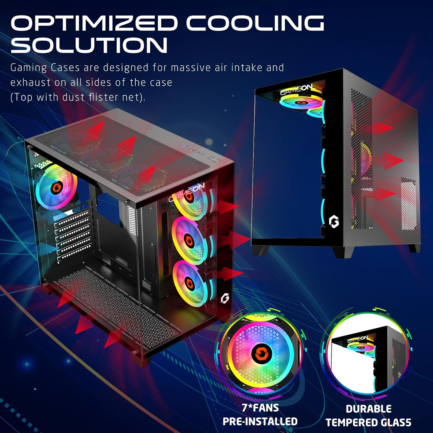
Figure 4.5: Optimized cooling solution diagram, illustrating airflow paths and the placement of pre-installed fans and dust filters.
The case comes with 7 pre-installed 120mm ARGB+PWM fans for optimal airflow. Additional fan and radiator support is available:
- Front: 3x 120mm fans (pre-installed)
- Top: 3x 120mm fans or 360mm radiator support
- Rear: 1x 120mm fan (pre-installed)
- Bottom: 3x 120mm fans
5. Setup and Installation
Follow these steps for proper component installation:
5.1 Preparing the Case
- Place the case on a flat, stable surface.
- Carefully remove the tempered glass side panel by unscrewing the thumb screws and sliding it off.
- Identify the accessory box containing screws and other small parts.
5.2 Motherboard Installation

Figure 5.1: Motherboard compatibility (ATX, M-ATX) and drive bay configurations (HDD/SSD).
- Install the necessary motherboard standoffs into the motherboard tray according to your motherboard's form factor (ATX, M-ATX).
- Place your motherboard onto the standoffs, aligning the screw holes.
- Secure the motherboard with the provided screws.
- Install the CPU cooler (if not already installed) ensuring it fits within the 165mm CPU clearance limit.
5.3 Graphics Card (GPU) Installation
- Remove the appropriate expansion slot covers from the rear of the case.
- Insert your graphics card into the PCIe slot on the motherboard.
- Secure the graphics card with screws. The case supports GPUs up to 410mm in length.
5.4 Storage Drive Installation
The case supports 2 HDDs and 1 SSD, or 1 HDD and 2 SSDs.
- Locate the drive bays/mounts for 3.5" HDDs and 2.5" SSDs.
- Mount your drives using the provided screws.
5.5 Cable Management and Connections
- Connect all power supply cables to your components (motherboard, GPU, drives).
- Connect the front panel I/O cables (USB 3.0, USB 2.0, Type-C, HD Audio, Power, Reset) to the corresponding headers on your motherboard. Refer to your motherboard manual for header locations.
- Utilize the cable routing cutouts and tie-down points behind the motherboard tray to manage cables neatly.
- Connect the ARGB+PWM fan cables to the fan controller or directly to your motherboard's ARGB/PWM headers if supported.
6. Operating Instructions
6.1 Powering On
- Ensure all components are correctly installed and cables are securely connected.
- Connect your monitor, keyboard, and mouse to the system.
- Plug the power supply cable into a wall outlet and turn on the power supply switch.
- Press the Power button on the top I/O panel of the case.
6.2 ARGB Lighting Control

Figure 6.1: ARGB+PWM fan control options, including motherboard sync compatibility and remote control functionality.
The pre-installed ARGB+PWM fans can be controlled in several ways:
- Remote Control: Use the included remote control to change lighting modes, colors, and fan speeds.
- Motherboard Software: If connected to a compatible ARGB header on your motherboard, you can synchronize lighting effects using motherboard manufacturer software (e.g., ASUS Aura Sync, MSI Mystic Light Sync, GIGABYTE RGB Fusion, ASRock Polychrome RGB).
- PWM Control: Fan speeds are automatically adjusted based on system temperature via PWM (Pulse Width Modulation) signals from the motherboard or fan controller.
7. Maintenance
Regular maintenance helps ensure optimal performance and longevity of your PC case.
- Dust Filters: The case includes dust filters. Regularly remove and clean these filters to maintain good airflow and prevent dust buildup inside the system. Use compressed air or a soft brush.
- Fan Cleaning: Periodically clean the fan blades with compressed air to remove dust. Ensure fans are not spinning while cleaning.
- Exterior Cleaning: Wipe down the exterior surfaces and tempered glass panels with a soft, damp cloth. Avoid abrasive cleaners.
8. Troubleshooting
If you encounter issues, refer to the following common troubleshooting steps:
| Problem | Possible Cause | Solution |
|---|---|---|
| System does not power on. | Loose power connections, faulty power supply, incorrect front panel wiring. | Check all power cables (PSU to wall, PSU to motherboard/components). Verify front panel power button wiring to motherboard. Test power supply. |
| Fans are not spinning or ARGB lighting is not working. | Loose fan/ARGB connections, faulty fan controller, incorrect motherboard header connection. | Ensure all fan power and ARGB cables are securely connected to the controller or motherboard. Check remote control battery. Verify motherboard ARGB header settings in BIOS/software. |
| Poor airflow or high temperatures. | Blocked dust filters, incorrect fan orientation, insufficient cooling. | Clean dust filters. Ensure fans are oriented correctly for intake/exhaust. Consider adding more fans or upgrading cooling solutions if temperatures remain high. |
9. Specifications
| Feature | Detail |
|---|---|
| Model | GO-EMPEROR-M |
| Case Type | Mid Tower |
| Motherboard Compatibility | ATX, M-ATX |
| Materials | SPCC, 0.7mm Tempered Glass |
| Dimensions (L x W x H) | 425 x 280 x 420 mm |
| Net Weight | 5.8 KG |
| GPU Length Limit | 410 mm |
| CPU Cooler Height Limit | 165 mm |
| Drive Bays | 2x HDD, 1x SSD (or 1x HDD, 2x SSD) |
| Expansion Slots | 7 |
| Pre-installed Fans | 7x 120mm ARGB+PWM Fans |
| Fan Support (Front) | 3x 120mm |
| Fan Support (Top) | 3x 120mm (or 360mm radiator) |
| Fan Support (Rear) | 1x 120mm |
| Fan Support (Bottom) | 3x 120mm |
| I/O Ports | 1x USB 3.0, 1x USB 2.0, 1x Type-C, HD Audio |
10. Warranty and Support
For warranty information and technical support, please refer to the official GAMEON website or contact your local retailer. Keep your proof of purchase for warranty claims.
For further assistance, visit the GAMEON Store on Amazon.


