
1. Introduction
This manual provides essential instructions for the safe and effective use of your Aoleaby JK Smart BMS Battery Protection Board, Model JK-BD 6A24S-8P. This device is designed to manage and protect Li-ion, Lipo, and LiFePo4 battery systems ranging from 8S to 24S configurations, offering active balancing and comprehensive protection features.
Please read this manual thoroughly before installation and operation to ensure proper functionality and to prevent damage to the BMS or your battery system.
2. Safety Information
- Always disconnect the battery system before performing any installation, maintenance, or wiring changes.
- Ensure all connections are correct and secure to prevent short circuits or damage. Incorrect wiring can lead to severe damage to the BMS, battery, or personal injury.
- Wear appropriate personal protective equipment (PPE), including insulated gloves and eye protection, when working with batteries.
- Do not expose the BMS to water, moisture, or extreme temperatures.
- Verify the voltage and current ratings of your battery pack are compatible with the BMS specifications.
- Keep out of reach of children.
3. Product Overview
The Aoleaby JK Smart BMS is an advanced battery management system featuring active balancing and multiple protection functions. It includes Bluetooth (BT) communication for real-time monitoring and configuration via a dedicated mobile application.

Figure 1: Aoleaby JK Smart BMS board with key connection points labeled.
Key Components and Ports:
- B-: Negative terminal for battery pack connection.
- P-: Negative terminal for load/charger connection.
- C-: Negative terminal for charger connection (if separate from load).
- Balance Ports (P1-P6): Connect to individual cell voltage detection wires. The number of pins varies based on the cell count (e.g., 8S-24S).
- D1: Temperature sensor port.
- QR Code: Scan this code to download the official JK BMS mobile application and access the user manual. The application allows for detailed monitoring and configuration of the BMS. Link: http://qr17.cn/BApbC0
4. Specifications
The JK Smart BMS Model JK-BD 6A24S-8P is designed for robust performance and protection.
| Feature | Description |
|---|---|
| Model | JK-BD 6A24S-8P |
| Supported Cell Count | 8S to 24S (Li-ion, Lipo, LiFePo4) |
| Max Current Range | 40A - 200A (depending on specific variant, this model supports up to 200A) |
| Active Balance Current | 0.6A - 2A |
| Communication | Bluetooth (BT) (RS485 optional, requires specific configuration) |
| Protection Functions | Over-charge, Over-discharge, Over-current, Short Circuit, Low Temperature Charging Cutoff |
| Dimensions (Approx.) | 1.18 x 0.79 x 0.39 inches (Package Dimensions) |
| Weight (Approx.) | 2.2 pounds |
5. Setup & Installation
Careful wiring is crucial for the correct operation and safety of the BMS. Refer to the wiring diagram below and follow these steps:
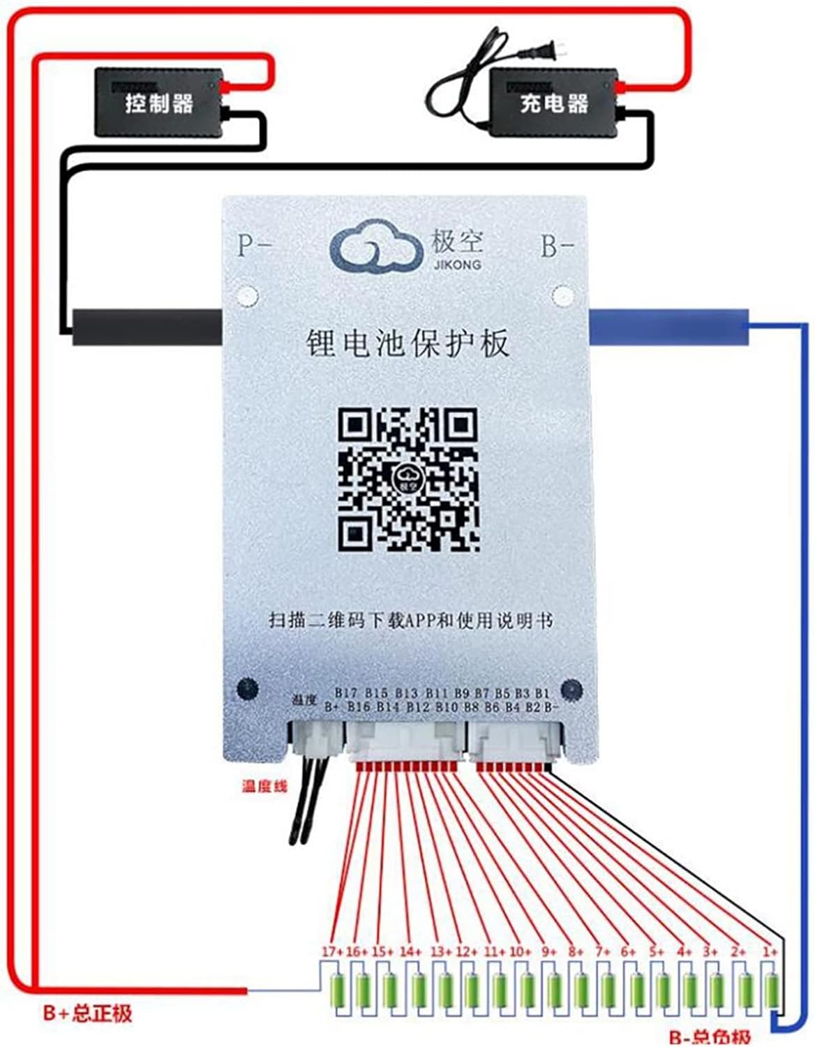
Figure 2: Wiring diagram for the Aoleaby JK Smart BMS.
Wiring Steps:
- Connect B-: Connect the main negative terminal of your battery pack to the B- port on the BMS. Ensure this connection is robust and capable of handling the full discharge current.
- Connect Balance Wires: Starting from B0 (the negative terminal of the first cell), connect each balance wire sequentially to the corresponding pins on the BMS balance ports (P1-P6). Ensure the order is correct (B0, B1, B2, ..., B+ total positive). Incorrect balance wire connection can damage the BMS.
- Connect P-: Connect the negative terminal of your load (e.g., inverter, motor) to the P- port on the BMS. This is the discharge path.
- Connect C- (Optional): If your charger requires a separate negative connection, connect it to the C- port. Otherwise, the charger can connect to P-.
- Connect Temperature Sensor: Plug the temperature sensor into the D1 port and place the sensor on or near the battery pack for accurate temperature monitoring.
- Connect B+: Connect the main positive terminal of your battery pack to the B+ terminal of your load/charger. The BMS does not typically manage the positive main connection directly.
Important: Always double-check all connections before applying power. Incorrect wiring can lead to irreversible damage.
6. Operation
The Aoleaby JK Smart BMS is primarily operated and monitored via its dedicated mobile application, which communicates via Bluetooth.
Using the Mobile Application:
- Download the App: Scan the QR code on the BMS unit or use the provided link (http://qr17.cn/BApbC0) to download and install the JK BMS application on your smartphone.
- Connect via Bluetooth: Enable Bluetooth on your phone. Open the JK BMS app and search for available BMS devices. Select your BMS to connect.
- Monitoring: The app provides real-time data on your battery system, including:
- Total battery voltage
- Individual cell voltages
- Charge/discharge current
- Battery temperature
- State of Charge (SOC)
- Active balancing status
- Settings and Configuration: The app allows you to adjust various parameters, such as:
- Over-charge/over-discharge voltage thresholds
- Over-current protection limits
- Temperature protection limits
- Balancing settings
Active Balancing:
The JK Smart BMS features active balancing to equalize the voltage differences between battery cells. This process helps maximize battery usage efficiency and extends the overall lifespan of the battery pack. The balancing status can be monitored through the mobile application.
7. Maintenance
- Regular Inspection: Periodically inspect all wiring connections for tightness and signs of corrosion or damage.
- Cleanliness: Keep the BMS unit clean and free from dust and debris. Use a dry, soft cloth for cleaning.
- Temperature Monitoring: Ensure the BMS and battery pack operate within their specified temperature ranges. Excessive heat can degrade performance and lifespan.
- Firmware Updates: Check the mobile application periodically for any available firmware updates for the BMS to ensure optimal performance and access to new features.
8. Troubleshooting
If you encounter issues with your JK Smart BMS, consider the following common problems and solutions:
| Problem | Possible Cause | Solution |
|---|---|---|
| BMS not powering on/no output | Incorrect wiring, main fuse blown, battery voltage too low. | Verify all wiring connections. Check main battery fuse. Charge battery pack to minimum voltage. |
| Cannot connect via Bluetooth | Bluetooth disabled on phone, BMS not powered, app issue. | Ensure Bluetooth is enabled. Verify BMS is powered. Restart app/phone. Try reinstalling the app. |
| Cell voltage imbalance | Initial imbalance, balance wires loose, active balancing not enabled. | Allow BMS time to balance. Check balance wire connections. Ensure active balancing is enabled in the app. |
| Over-charge/discharge protection triggered | Battery voltage exceeded limits, protection settings too strict. | Check battery voltage. Adjust protection thresholds in the app if necessary (with caution). |
| Over-current protection triggered | Load current too high, short circuit. | Reduce load. Check for short circuits in the system. Adjust over-current limit in the app if appropriate for your system. |
If the problem persists, contact customer support for further assistance.
9. Warranty & Support
Aoleaby products are manufactured to high-quality standards. For specific warranty information, please refer to the product packaging or the retailer's terms of sale. Keep your purchase receipt as proof of purchase.
For technical support or inquiries, please contact your point of purchase or visit the Aoleaby official website for contact information.