
AITRIP ESP32-3248S035C
User Manual: AITRIP 3.5 inch ESP32 Display Module
Model: ESP32-3248S035C
1. Introduction
This manual provides comprehensive instructions for the AITRIP 3.5 inch ESP32 Display Module (Model: ESP32-3248S035C). This development board integrates an ESP32-DOWDQ6 controller with a 3.5-inch 320x480 resistive touch TFT LCD, making it suitable for a wide range of IoT applications requiring a graphical user interface. It features a dual-core CPU, rich peripheral interfaces, and supports various communication protocols.

Figure 1.1: The AITRIP 3.5 inch ESP32 Display Module shown with its accompanying USB cable, 4P terminal cable, and touch pen. This image provides an overview of the complete product package.
2. Package Contents
Verify that all items listed below are present in your package. If any components are missing or damaged, please contact customer support.
- 1 x ESP32 3.5 inch TFT Touch Screen Display Module
- 1 x USB Cable
- 1 x Touch Pen (Stylus)
- 1 x 4P Terminal Cable
- 1 x Transparent Storage Box
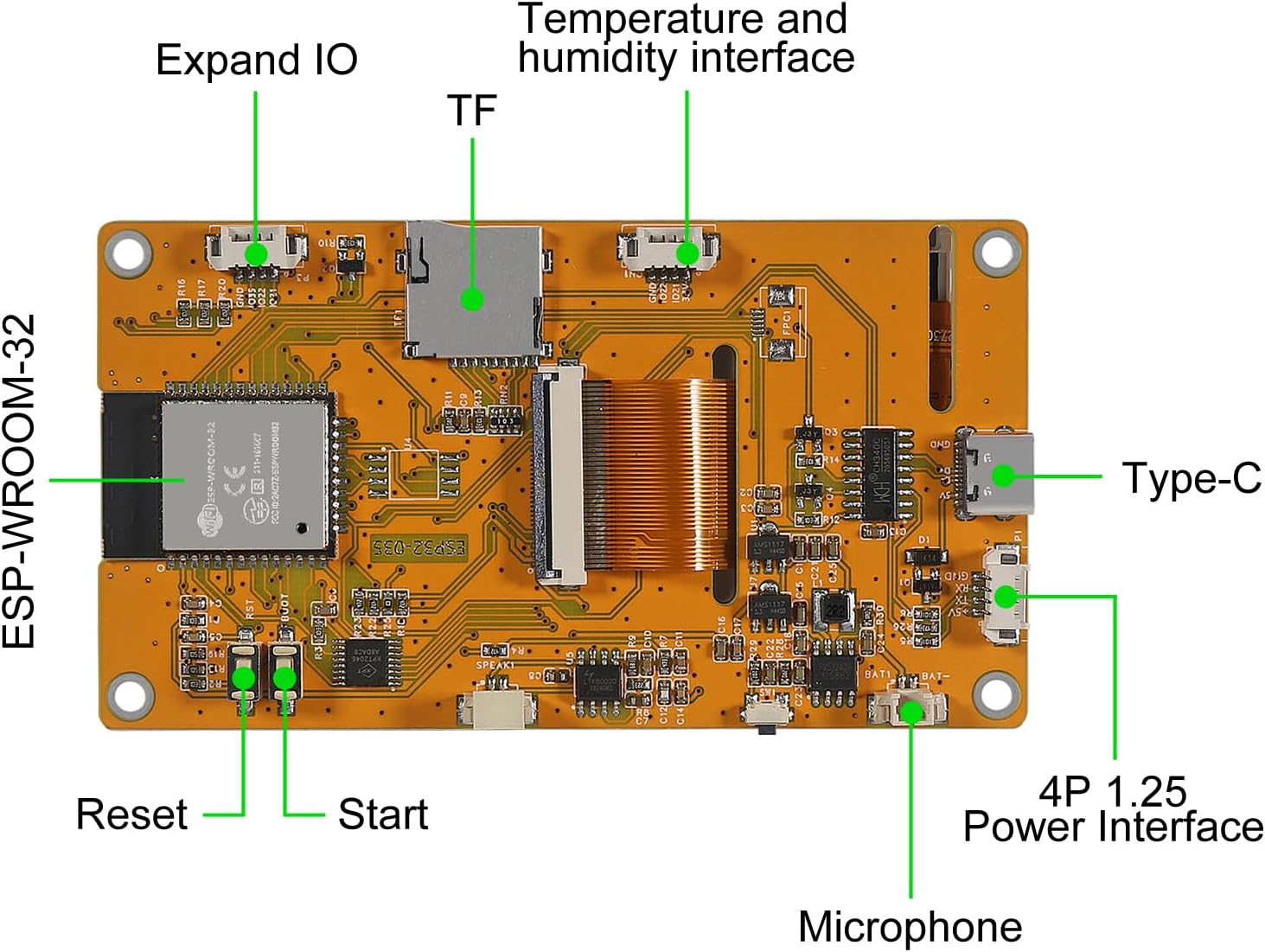
Figure 2.1: Visual representation of the components included in the package: the 3.5-inch LCD TFT Module, USB Data Cable, 2P Power Cord, Stylus, and Transparent Storage Box.
3. Setup
3.1. Physical Overview
Familiarize yourself with the various ports and components on the ESP32 Display Module.

Figure 3.1: Rear view of the ESP32 Display Module, highlighting the ESP-WROOM-32 module, TF card slot, Type-C USB port, 4P 1.25 Power Interface, Microphone, Reset button, Start button, Expand IO pins, and Temperature and Humidity interface.
3.2. Connecting the Module
- Power Connection: Connect the provided USB cable to the Type-C port on the module and to a 5V power source (e.g., a computer USB port or a USB power adapter). Alternatively, use the 4P terminal cable for external power supply.
- Data Connection: When connecting to a computer for programming, ensure the USB cable is securely connected.
- TF Card Insertion: If using a TF card for storage or data logging, gently insert it into the designated TF card slot until it clicks into place.
- Peripheral Connections: Utilize the Expand IO pins for connecting external sensors, actuators, or other components as required by your project.
3.3. Software Environment Setup
The ESP32 Display Module is compatible with the Arduino IDE for programming. Follow these steps to set up your development environment:
- Install Arduino IDE: Download and install the latest version of the Arduino IDE from the official Arduino website (www.arduino.cc/en/software).
- Add ESP32 Board Manager URL:
- Go to File > Preferences in the Arduino IDE.
- In the "Additional Boards Manager URLs" field, add:
https://raw.githubusercontent.com/espressif/arduino-esp32/gh-pages/package_esp32_index.json - Click OK.
- Install ESP32 Boards:
- Go to Tools > Board > Boards Manager...
- Search for "ESP32" and install the "esp32 by Espressif Systems" package.
- Install Libraries: Depending on your project, you may need to install specific libraries for the display (e.g., TFT_eSPI, LovyanGFX) and touch functionality. These can typically be found via the Arduino Library Manager (Sketch > Include Library > Manage Libraries...).
- Select Board and Port:
- Connect the ESP32 module to your computer via USB.
- Go to Tools > Board and select the appropriate ESP32 board (e.g., "ESP32 Dev Module").
- Go to Tools > Port and select the serial port corresponding to your connected ESP32 module.
4. Operating the Module
4.1. Basic Functionality
The ESP32 Display Module is designed for various applications, leveraging its integrated display and ESP32 capabilities.

Figure 4.1: The front of the ESP32 Display Module, illustrating a sample graphical user interface with various application icons such as Image, Slider, Curve, Switch, Downloads, Text, Pointer, and Power.
The module can be used for:
- Remote Environment Data Collection: Connect sensors to gather data (e.g., temperature, humidity) and display it on the screen or transmit it wirelessly.
- Remote Data Fusion: Combine data from multiple sources for display and analysis.
- Remote Parameter Settings: Adjust device parameters remotely via the display interface.
- Home Smart Device Control: Act as a central control panel for smart home devices, including image transmission from cameras.
- Wireless Positioning Systems: Integrate into systems requiring signal processing and display.

Figure 4.2: The ESP32 Display Module in a typical development scenario, connected to a laptop via USB. This setup demonstrates its use for remote control of applications, environmental data collection, data fusion, and parameter setting.
4.2. Programming and Development
The ESP32-DOWDQ6 controller supports a wide array of functionalities for secondary development:
- Interfaces: UART, SPI, I2C, PWM, ADC, DAC.
- Camera Support: Compatible with OV2640 and OV7670 cameras, with built-in flash support.
- Connectivity: Image WiFi upload, STA/AP/STA+AP working modes, AirKiss one-click network configuration.
- Storage: TF card support for data logging and asset storage.
- Power Management: Multiple sleep modes for low-power applications.
- Operating System: Embedded LWip and FreeRTOS for robust application development.
- CPU: Low-power dual-core 32-bit CPU for application processing.
Refer to the extensive ESP32 documentation and community resources for detailed programming guides and examples.
5. Maintenance
Proper maintenance ensures the longevity and optimal performance of your ESP32 Display Module.
- Cleaning: Use a soft, dry, lint-free cloth to gently wipe the display screen and module surface. Avoid using abrasive cleaners, solvents, or aerosol sprays, as these can damage the components.
- Storage: When not in use, store the module in its transparent storage box or an anti-static bag to protect it from dust, moisture, and electrostatic discharge. Store in a cool, dry place away from direct sunlight and extreme temperatures.
- Handling: Always handle the module by its edges to avoid touching the sensitive electronic components or the display surface directly.
- Power Off: Disconnect power before making any physical connections or disconnections to the module.
6. Troubleshooting
This section addresses common issues you might encounter with the ESP32 Display Module.
| Problem | Possible Cause | Solution |
|---|---|---|
| Module does not power on. | Incorrect power connection; faulty USB cable; insufficient power supply. | Ensure USB cable is securely connected. Try a different USB port or power adapter. Verify power supply provides stable 5V. |
| Display remains blank or shows garbage. | Incorrect display initialization code; faulty connections; incompatible library. | Check your Arduino code for correct display initialization (e.g., ST7796 driver). Ensure all connections are secure. Verify you are using compatible display libraries. |
| Cannot upload code to ESP32. | Incorrect board/port selection in Arduino IDE; missing drivers; module not in programming mode. | Select the correct ESP32 board and COM port. Install necessary USB-to-serial drivers (e.g., CP210x or CH340). Press and hold the "BOOT" button (often labeled "Start") while pressing "RESET", then release "RESET" and then "BOOT" to enter programming mode before uploading. |
| Touch screen is unresponsive or inaccurate. | Incorrect touch screen calibration; faulty touch controller library; physical damage. | Implement touch screen calibration in your code. Ensure you are using the correct touch screen library for resistive touch. Inspect for physical damage. |
| Wi-Fi or Bluetooth connectivity issues. | Incorrect network credentials; interference; antenna issues. | Double-check Wi-Fi SSID and password. Ensure the module is within range of the Wi-Fi network. Avoid placing the module near strong electromagnetic interference sources. |
7. Specifications
Detailed technical specifications for the AITRIP 3.5 inch ESP32 Display Module.
| Feature | Description |
|---|---|
| Brand | AITRIP |
| Model Name | ESP32-2432S028R (also referred to as ESP32-3248S035C) |
| Controller | ESP32-DOWDQ6 (ESP-WROOM-32) |
| Display Size | 3.5 inches |
| Resolution | 320x480 pixels |
| Display Type | TFT LCD |
| Touch Screen Type | Resistive Touch |
| Display Driver IC | ST7796 (as per product title, though feature bullet mentions ILI9341 for ESP32-2432S028R) - Note: Verify specific driver IC for your module version. |
| CPU | Low-power dual-core 32-bit CPU |
| Clock Frequency | Up to 240MHz |
| Connectivity Technology | Wi-Fi, USB, I2C (also SPI, UART, PWM, ADC, DAC) |
| Operating System | FreeRTOS (Embedded LWip) |
| Camera Support | OV2640 and OV7670 (with built-in flash) |
| Storage | TF Card slot |
| Power Interface | Type-C USB, 4P 1.25 Power Interface |
7.1. Dimensions

Figure 7.1: The physical dimensions of the module, showing a length of 101mm (3.97 inches) and a width of 55mm (2.16 inches).
7.2. Schematic Diagram
For advanced users and developers, the schematic diagram provides detailed circuit information.

Figure 7.2: A detailed schematic diagram of the ESP32 Display Module, illustrating power circuits, USB to TTL converter, ESP32 connections, TFT display interface, ADC, LED-RGB, and Flash memory connections. This diagram is useful for in-depth understanding and debugging.
8. Warranty and Support
For product support, technical assistance, or warranty inquiries, please contact AITRIP customer service.
To reach support, navigate to the product page on Amazon.com, locate "Sold by Aitrip" (usually under the "Buy Now" button), click on "Aitrip", and then select "Ask a question" on the new page.
Ask a question about this manual
Ask about setup, troubleshooting, compatibility, parts, safety, or missing instructions. Manuals+ will review the question and use this page’s manual context to help answer it.