
1. Introduction
This manual provides essential information for the safe and efficient operation of your DEWIN 380V 1.5kW Variable Frequency Drive (VFD) inverter. This industrial-grade inverter is designed for precise motor speed control in various applications, including fans, pumps, compressors, conveyors, and grinding machines. Please read this manual thoroughly before installation, operation, or maintenance to ensure proper usage and prevent damage or injury.

Figure 1: Front view of the DEWIN 380V 1.5kW VFD Inverter, showing the display panel and control buttons.
2. Safety Information
Always observe the following safety precautions to prevent electric shock, fire, or personal injury:
- Ensure the power supply is disconnected before any wiring or maintenance.
- Wait at least 10 minutes after removing power before servicing to allow capacitors to discharge.
- Do not connect AC power to the output terminals (U/T1, V/T2, W/T3).
- Installation and wiring must be performed by qualified personnel only.
- Ensure proper grounding to prevent electric shock.
- Do not operate the inverter with damaged cables or if the casing is open.
- Keep the inverter away from water, direct sunlight, and corrosive environments.
3. Product Overview
3.1 Components and Controls
The VFD inverter features a clear display and intuitive control buttons for easy operation.

Figure 2: Detailed view of the inverter's control panel, indicating the status display area, numeric up key, frequency setting knob, value down key, run key, stop/reset button, and parameter data setting button.
- Status Display Area: Shows current frequency, voltage, current, and other operational parameters.
- Numeric Up Key (▲): Used to increase numerical values or navigate menus.
- Frequency Setting Knob: Adjusts the output frequency.
- Value Down Key (▼): Used to decrease numerical values or navigate menus.
- PRG (Program) Button: Enters or exits parameter setting mode.
- ENTER Button: Confirms selections or enters sub-menus.
- RUN Button: Starts motor operation.
- STOP/RST (Stop/Reset) Button: Stops motor operation or resets fault alarms.
4. Setup
4.1 Mounting
The inverter is designed for wall-mounted installation. Ensure the mounting surface is stable and allows for adequate ventilation around the unit. Maintain sufficient clearance for cooling air circulation.
4.2 Wiring Instructions
Proper wiring is crucial for safe and correct operation. Refer to the diagrams below for connecting the power supply and motor.

Figure 3: Basic wiring diagram for the 380V inverter, showing connections for a single-phase 380V power supply, ground wire, and a three-phase motor.

Figure 4: Detailed wiring diagram illustrating the connection from a household AC 380V supply via a switch to the frequency converter (inverter), and then to a three-phase asynchronous motor. Input terminals are L1, L2, and output terminals are U, V, W.
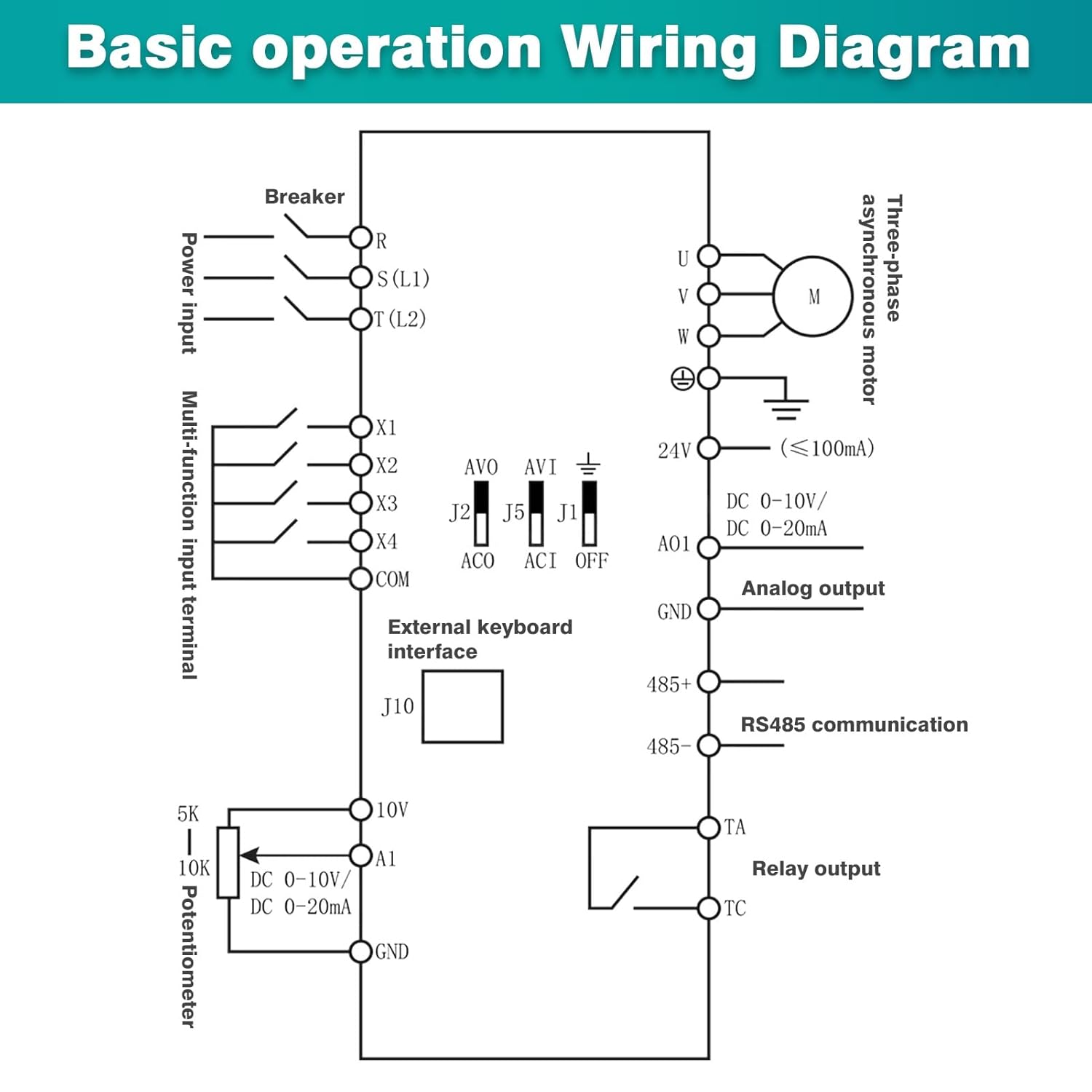
Figure 5: Comprehensive wiring schematic for basic operation, including power input (R, S(L1), T(L2)), multi-function input terminals (X1-X4, COM), external keyboard interface (J10), analog output (AO1, GND), RS485 communication (485+, 485-), relay output (TA, TC), and potentiometer connections (10V, A1, GND).
- Connect the single-phase 380V AC power supply to the input terminals (L1, L2).
- Connect the three-phase motor to the output terminals (U, V, W).
- Ensure the ground wire is securely connected to the designated ground terminal.
- For external control, connect multi-function input terminals (X1-X4) and potentiometer as per your application requirements, referring to Figure 5.
- Double-check all connections for tightness and correctness before applying power.
5. Operating Instructions
5.1 Initial Power-Up
- After completing all wiring, apply power to the inverter.
- The display will light up, showing the default frequency or last set value.
5.2 Setting Parameters
To adjust operational parameters:
- Press the PRG button to enter parameter setting mode.
- Use the Numeric Up (▲) and Value Down (▼) keys to navigate through parameters.
- Press ENTER to select a parameter for editing.
- Use the Numeric Up (▲) and Value Down (▼) keys or the Frequency Setting Knob to change the value.
- Press ENTER again to save the new value.
- Press PRG to exit parameter setting mode.
5.3 Starting and Stopping the Motor
- To start the motor, press the RUN button. The display will show the operating frequency.
- To stop the motor, press the STOP/RST button.
5.4 Key Features
- Current Limiting: The inverter features rapid current limiting to prevent frequent overcurrent alarms. When current exceeds the protection point, it quickly limits the current to protect equipment and avoid alarms caused by sudden loads or interference.
- Multiple Control Algorithms: Supports VF control for asynchronous motors, open-loop current vector control, standard open-loop permanent magnet synchronous motor control, and open-loop vector control. Provides 150% starting torque at 0.5Hz (sensorless V/F control).
- Torque Limitation: Limits the rotation path to the maximum set path if the trajectory command exceeds the machine's maximum rotational resistance, ensuring equipment safety.
6. Maintenance
Regular maintenance ensures the longevity and reliable operation of your VFD inverter.
- Cleaning: Periodically clean the inverter's exterior and cooling fan vents to prevent dust accumulation, which can hinder heat dissipation. Use a soft, dry cloth. Do not use liquid cleaners.
- Inspection: Regularly inspect wiring connections for tightness and signs of wear or damage. Check for any unusual noises or odors during operation.
- Cooling Fan: The inverter features independent cooling air channels and a high-speed fan for efficient heat dissipation. Ensure these channels are unobstructed.
- Storage: If storing the inverter, keep it in a dry, dust-free environment within the specified temperature range.
7. Troubleshooting
This section addresses common issues you might encounter. For problems not listed here, contact technical support.
| Problem | Possible Cause | Solution |
|---|---|---|
| Motor does not start | No power, incorrect wiring, parameter settings, or fault alarm. | Check power supply, verify wiring, review parameter settings, and clear any fault alarms using the STOP/RST button. |
| Overcurrent alarm | Motor overload, short circuit, or rapid acceleration. | Reduce motor load, check motor and wiring for short circuits, adjust acceleration time in parameters. |
| Overvoltage alarm | Input voltage too high, or rapid deceleration. | Verify input voltage is within specifications, increase deceleration time in parameters. |
| Undervoltage alarm | Input voltage too low. | Check input power supply voltage. |
| Overheat alarm | Insufficient ventilation, high ambient temperature, or blocked cooling fan. | Ensure proper ventilation, clean fan and heatsink, reduce ambient temperature if possible. |
8. Specifications
The following table details the technical specifications of the DEWIN 380V 1.5kW VFD Inverter.

Figure 6: Image displaying the dimensions of the inverter (140mm height, 70mm width, 115mm depth) and a table of key specifications.
| Parameter | Value |
|---|---|
| Material | Flame retardant ABS plastic |
| Input Rated Voltage | Single-phase 380V |
| Input Rated Frequency | 50/60 Hz |
| Input Rated Current | 5.0 A |
| Output Rated Voltage | Three-phase 380V |
| Output Rated Current | 3.7 A |
| Output Frequency (Low Frequency Mode) | 0 ~ 320 Hz |
| Applicable Motor Power | 1.5 kW |
| Installation Method | Wall-mounted |
| Protection Level | IP20 |
| Cooling Method | Cooling fan |
| Dimensions (L x W x H) | 11.5 x 7.3 x 14.2 cm (approx. 3 x 2 x 1 cm in product data, using image data for clarity) |
| Weight | 840 Grams |
| Model Number | KDMFBZDBB-GS110208-03 |
9. Warranty and Support
For warranty information and technical support, please refer to the documentation provided with your purchase or contact DEWIN customer service. Information regarding spare parts availability is not provided in the product details.