Introduction
This manual provides essential information for setting up, operating, maintaining, and troubleshooting your DORHEA ESP32-C3 Mini Development Board. The ESP32-C3 is a compact, high-performance, and low-power IoT development board featuring a 32-bit RISC-V single-core processor with FPU, integrated 2.4 GHz Wi-Fi (802.11b/g/n), and Bluetooth 5 (LE) connectivity. It is designed for various low-power IoT and wireless wearable applications.
The board offers rich interfaces, including 11 digital I/Os (usable as PWM pins) and 4 analog I/Os (usable as ADC pins), along with support for UART, I2C, and SPI serial interfaces.
Key Features
- Powerful CPU: ESP32-C3, 32-bit RISC-V single-core processor, operating up to 160 MHz with FPU for 32-bit single-precision operations.
- Wireless Connectivity: Integrated 802.11b/g/n Wi-Fi (2.4GHz) supporting Station mode, SoftAP mode, SoftAP+Station mode, and hybrid mode. Bluetooth 5.0 (LE) is also included.
- Ultra-low Power Consumption: Designed for low-power applications with deep sleep power consumption of approximately 43µA.
- Memory: 400KB SRAM, 384KB ROM, and built-in 4MB flash.
- Rich Board Resources: 11 digital I/Os (PWM capable) and 4 analog I/Os (ADC capable).
- Serial Interfaces: Supports UART, I2C, and SPI.
- Security Features: Encryption hardware accelerators supporting AES-128/256, hashing, RSA, HMAC, digital signatures, and secure startup.
- Onboard LED: Blue LED connected to GPIO8.
- Compact Design: Positioned as a high-performance, low-power, cost-effective IoT mini development board.
Setup
1. Unpacking and Inspection
Carefully remove the ESP32-C3 Mini Development Board from its packaging. Inspect the board for any visible damage or missing components. The package typically includes two ESP32-C3 development boards.

Image: Two DORHEA ESP32-C3 Mini Development Boards, showing their compact size and pin headers.
2. Pin Header Installation (for unwelded pins)
If your boards come with unwelded pins, you will need to solder the provided pin headers onto the board. Ensure proper alignment before soldering to allow for easy integration into breadboards or custom PCBs.

Image: Side view of the ESP32-C3 Mini Development Board with pin headers attached, illustrating how the pins extend downwards for breadboard compatibility.
3. Identifying Board Components
Familiarize yourself with the layout of the board. Key components include the ESP32-C3 chip, USB Type-C port, BOOT button, RST (Reset) button, and various GPIO pins.
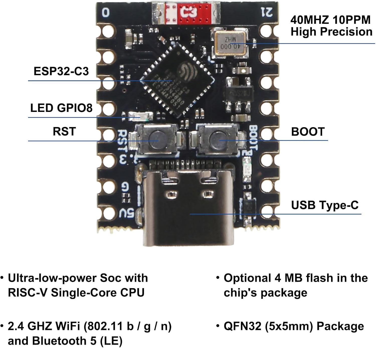
Image: A detailed diagram labeling the key components of the ESP32-C3 Mini Development Board, including the ESP32-C3 chip, LED GPIO8, RST button, BOOT button, USB Type-C port, and 40MHz 10PPM High Precision crystal.
4. Driver Installation and IDE Setup
To program the ESP32-C3 Mini Development Board, you will need to install the appropriate USB-to-Serial drivers for your operating system (if not automatically detected) and set up your preferred Integrated Development Environment (IDE), such as Arduino IDE or Espressif IDF. Refer to Espressif's official documentation for detailed instructions on setting up the development environment for ESP32-C3.
5. Connecting to Computer
Connect the ESP32-C3 Mini Development Board to your computer using a USB Type-C cable. The board should be recognized as a serial port.
Operating Instructions
1. Basic Programming
Once your development environment is set up, you can write and upload code to the ESP32-C3.
- Select the correct board model (ESP32-C3 Dev Module) and serial port in your IDE.
- Write your program (sketch) using C/C++ or MicroPython.
- Compile and upload the code to the board.
2. Entering Bootloader Mode for Flashing
If the board does not connect or flash correctly, it may be necessary to manually put it into bootloader mode.
- Press and hold the BOOT button.
- While holding BOOT, briefly press the RST button.
- Release the BOOT button. The board is now in bootloader mode and ready to receive new firmware.
3. Pinout Diagram
The following diagram illustrates the pinout of the ESP32-C3 Mini Development Board, indicating power, ground, analog, digital, and communication pins.

Image: A color-coded pinout diagram for the ESP32-C3 Super Mini, showing the allocation of pins for GND, Pin No, Power, ADC, SPI, Digital, and UART functions.
Maintenance
- Storage: Store the development board in an anti-static bag when not in use to prevent electrostatic discharge (ESD) damage.
- Cleaning: Use a soft, dry brush or compressed air to remove dust. Avoid using liquids or abrasive cleaners.
- Handling: Handle the board by its edges to minimize contact with components and prevent ESD.
- Power Supply: Ensure a stable and correct voltage power supply (5V via USB-C) to prevent damage to the board.
Troubleshooting
- Board not recognized by computer:
- Ensure USB Type-C cable is fully inserted and functional.
- Verify that the correct USB-to-Serial drivers are installed for your operating system.
- Try a different USB port or computer.
- Failed to upload code / Board keeps disconnecting:
- This often occurs when the board has no firmware or corrupted firmware. Manually put the board into bootloader mode before uploading (press and hold BOOT, then press RST, then release BOOT).
- Ensure the correct board and serial port are selected in your IDE.
- Check for any error messages in the IDE's output window.
- Wi-Fi connectivity issues:
- Ensure your code correctly initializes and connects to the Wi-Fi network.
- Check the Wi-Fi signal strength in your environment.
- Consider reducing Wi-Fi transmit power in your code if experiencing instability, especially in close proximity to other devices.
- LED (GPIO8) not lighting up:
- Verify that your code is correctly configured to control GPIO8.
- Check for any short circuits or incorrect wiring if external components are connected.
Specifications
| Feature | Detail |
|---|---|
| Processor | ESP32-C3, 32-bit RISC-V Single-Core, up to 160 MHz |
| RAM | 400KB SRAM |
| ROM | 384KB ROM |
| Flash Memory | Built-in 4MB Flash |
| Wireless Connectivity | Wi-Fi (802.11b/g/n 2.4GHz), Bluetooth 5.0 (LE) |
| Operating System | FreeRTOS (common for ESP32) |
| I/O Pins | 11 Digital I/Os (PWM), 4 Analog I/Os (ADC) |
| Serial Interfaces | UART, I2C, SPI |
| Onboard LED | Blue LED on GPIO8 |
| Power Consumption | Ultra-low power, approx. 43µA in deep sleep |
| Dimensions | Approx. 24mm x 18mm (0.94in x 0.70in) |
| Weight | Approx. 0.48 ounces |

Image: A top-down view of the ESP32-C3 Mini Development Board with measurements indicating its length (24mm/0.94in) and width (18mm/0.70in).
Warranty and Support
For specific warranty information, technical support, or further assistance with your DORHEA ESP32-C3 Mini Development Board, please refer to the manufacturer's official website or contact the seller directly through the platform where the product was purchased. Keep your purchase receipt or order details handy for any warranty claims.


