1. Introduction
Thank you for purchasing the KATO 22-050 ECS-1 Driving Stand Type Controller AC Adapter Set. This controller is designed to provide a realistic and immersive operating experience for your model railway. This manual will guide you through the setup, operation, and maintenance of your new controller to ensure safe and enjoyable use.
2. Safety Information
- Always disconnect the power supply before performing any maintenance or cleaning.
- Do not expose the controller to water or excessive moisture.
- Use only the provided KATO AC adapter or a compatible power supply specified by the manufacturer.
- Keep the device away from direct sunlight and heat sources.
- This product is not a toy. It is intended for use by individuals aged 14 and older.
- Ensure proper ventilation around the unit during operation.
3. Package Contents
Please check that all the following items are included in your package:
- KATO 22-050 ECS-1 Driving Stand Type Controller
- AC Adapter
- Instruction Manual (this document)
4. Product Overview
Familiarize yourself with the various parts of your KATO 22-050 ECS-1 controller.

Figure 4.1: Front-Side View
This image displays the primary operating side of the controller, featuring the main control lever on the right, three circular gauges (likely for speed, pressure, and current) on the angled panel, and a row of indicator lights below the gauges.

Figure 4.2: Opposite Front-Side View
Another perspective of the controller's front, highlighting the ergonomic design of the control lever and the clear visibility of the gauges and status indicators.

Figure 4.3: Rear View
The rear panel of the controller, showing the power input jack, ventilation grilles, and output terminals for connecting to the model railway track. An AC adapter cable is visible.
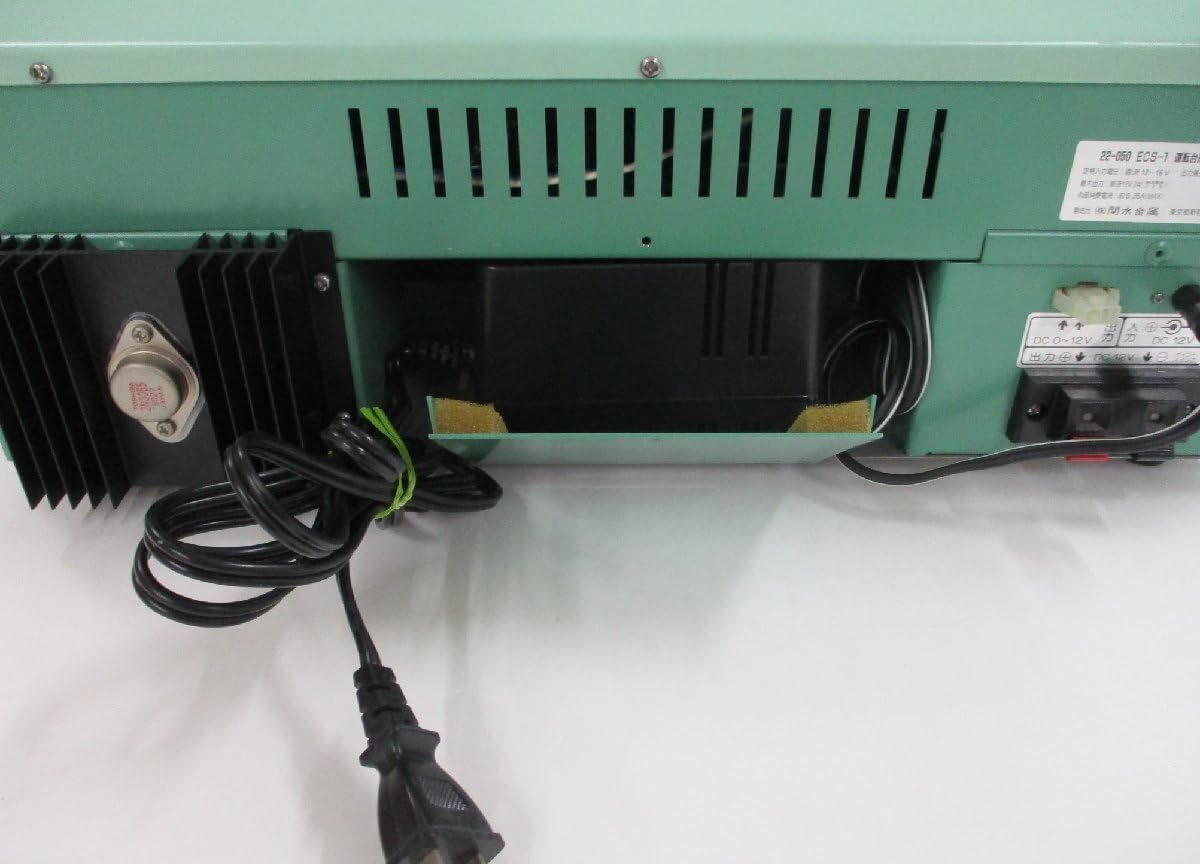
Figure 4.4: Rear Panel Detail
A closer look at the rear connections, including the AC adapter input and the DC output terminals for track power. Labels indicate DC 0-12V output.

Figure 4.5: Gauges and Indicators
This detailed view shows one of the gauges indicating speed in km/h, ranging up to 160 km/h. Below the gauges are several indicator lights with labels such as 'Overcurrent', 'Speed Control', 'Direct Current', 'Electric Brake', and 'Emergency'.

Figure 4.6: Indicator Lights Detail
A close-up of the indicator lights. From left to right, the labels are: 'Overcurrent' (過電流), 'Speed Control' (抑速), 'Direct Current' (直通), 'Electric Brake' (電制), and 'Emergency' (非常). In this image, 'Overcurrent' and 'Direct Current' appear to be illuminated.

Figure 4.7: Control Lever Base
A detailed view of the mounting mechanism for the main control lever, showing its robust construction.

Figure 4.8: Bottom View
The underside of the controller, revealing rubber feet for stability and additional ventilation slots.
5. Setup
- Placement: Place the KATO 22-050 ECS-1 controller on a stable, flat surface, ensuring adequate ventilation around the unit.
- Connect AC Adapter: Insert the plug of the supplied AC adapter into the 'AC IN' jack on the rear of the controller (refer to Figure 4.3 and 4.4). Then, plug the AC adapter into a standard wall outlet.
- Connect to Track: Connect the track feeder wires from your model railway layout to the 'DC 0-12V' output terminals on the rear of the controller. Ensure correct polarity (+ and -) as indicated on the terminals and your track system.
- Initial Check: Before operating, ensure all connections are secure and there are no loose wires.
6. Operating Instructions
The KATO 22-050 ECS-1 controller simulates a real train cab experience. Follow these steps for operation:
6.1 Power On/Off
- To power on, ensure the AC adapter is connected and plugged into a live outlet. The controller should illuminate its internal indicators.
- To power off, simply unplug the AC adapter from the wall outlet.
6.2 Main Control Lever
The large lever on the right side of the controller is your primary control for speed and braking.
- Acceleration: Push the lever forward to increase the train's speed. The speed gauge (km/h) will indicate the simulated speed.
- Braking/Deceleration: Pull the lever backward to decrease the train's speed or apply brakes.
- Neutral: Position the lever in the center for a neutral state where no power is supplied to the track.
6.3 Gauges
The three circular gauges provide visual feedback on the train's status:
- Speed Gauge (km/h): Indicates the simulated speed of the train.
- Other Gauges: These may represent parameters such as brake pressure, current draw, or other operational metrics. Refer to specific KATO documentation for detailed interpretation if available.
6.4 Indicator Lights
The row of indicator lights provides important status information (refer to Figure 4.5 and 4.6):
- Overcurrent (過電流): Illuminates if the current draw exceeds safe limits, indicating a short circuit or overload on the track. Immediately reduce power or investigate the cause.
- Speed Control (抑速): May indicate an active speed control function or mode.
- Direct Current (直通): Likely indicates that direct current power is being supplied to the track.
- Electric Brake (電制): Illuminates when the electric braking system is active.
- Emergency (非常): Illuminates during an emergency stop condition. There may be an associated emergency stop button (red button visible in Figure 4.5) that activates this.
7. Maintenance
- Cleaning: Use a soft, dry cloth to wipe the exterior of the controller. Do not use abrasive cleaners or solvents.
- Storage: When not in use, store the controller in a clean, dry place, away from dust and extreme temperatures.
- Inspection: Periodically check the power cord and adapter for any signs of damage. If damaged, discontinue use and replace with an authorized KATO part.
8. Troubleshooting
| Problem | Possible Cause | Solution |
|---|---|---|
| Controller does not power on. | AC adapter not connected or faulty. No power from outlet. | Ensure AC adapter is securely connected to the controller and plugged into a working outlet. Test the outlet with another device. |
| Train does not move. | Track connections loose. Overcurrent detected. Control lever in neutral. | Check track feeder connections. If 'Overcurrent' light is on, check for short circuits on the track or locomotive. Move the control lever forward. |
| Train moves erratically. | Dirty track or locomotive wheels. Loose connections. | Clean track and locomotive wheels. Ensure all connections are tight. |
| 'Overcurrent' light illuminates frequently. | Short circuit on track. Locomotive drawing too much current. | Inspect track for foreign objects or derailments causing a short. Check locomotive for issues. Reduce the number of locomotives if multiple are used. |
9. Specifications
- Model: KATO 22-050 ECS-1
- Input Power: AC (via dedicated AC adapter)
- Output Power: DC 0-12V (for track)
- Control Type: Driving Stand Type (Lever control)
- Indicators: Speed gauge (km/h), Overcurrent, Speed Control, Direct Current, Electric Brake, Emergency lights.
10. Warranty and Support
For warranty information and customer support, please refer to the documentation provided at the time of purchase or contact your retailer. KATO provides support for its products, and details can typically be found on their official website or through authorized distributors.


