1. Introduction
The Radiomaster ER4 2.4GHz 4CH ExpressLRS (ELRS) PWM Receiver is engineered for high performance, reliability, and flexible configuration in various remote-controlled applications. Based on the revolutionary ExpressLRS system, it offers fast response speeds and ultra-long range capabilities. This receiver is designed to provide precise control and essential telemetry data for fixed-wing aircraft, RC cars, boats, and tanks.
Key features include built-in receiver voltage telemetry, flight battery telemetry with automatic voltage detection, and support for Wi-Fi updates and WEBUI configuration. Its robust design ensures durability and ease of use for enthusiasts and hobbyists.

Figure 1: Radiomaster ER4 PWM Receiver highlighting its compact design. This receiver is lightweight and small, making it suitable for various small aircraft, boats, and cars.
2. Package Contents
- 1x Radiomaster ER4 2.4GHz 4CH ExpressLRS ELRS PWM Receiver
- 1x Voltage Telemetry Wire
- 1x CRSF Wire
- 1x ELRS-RX-SBUS Wire
- 1x User Card
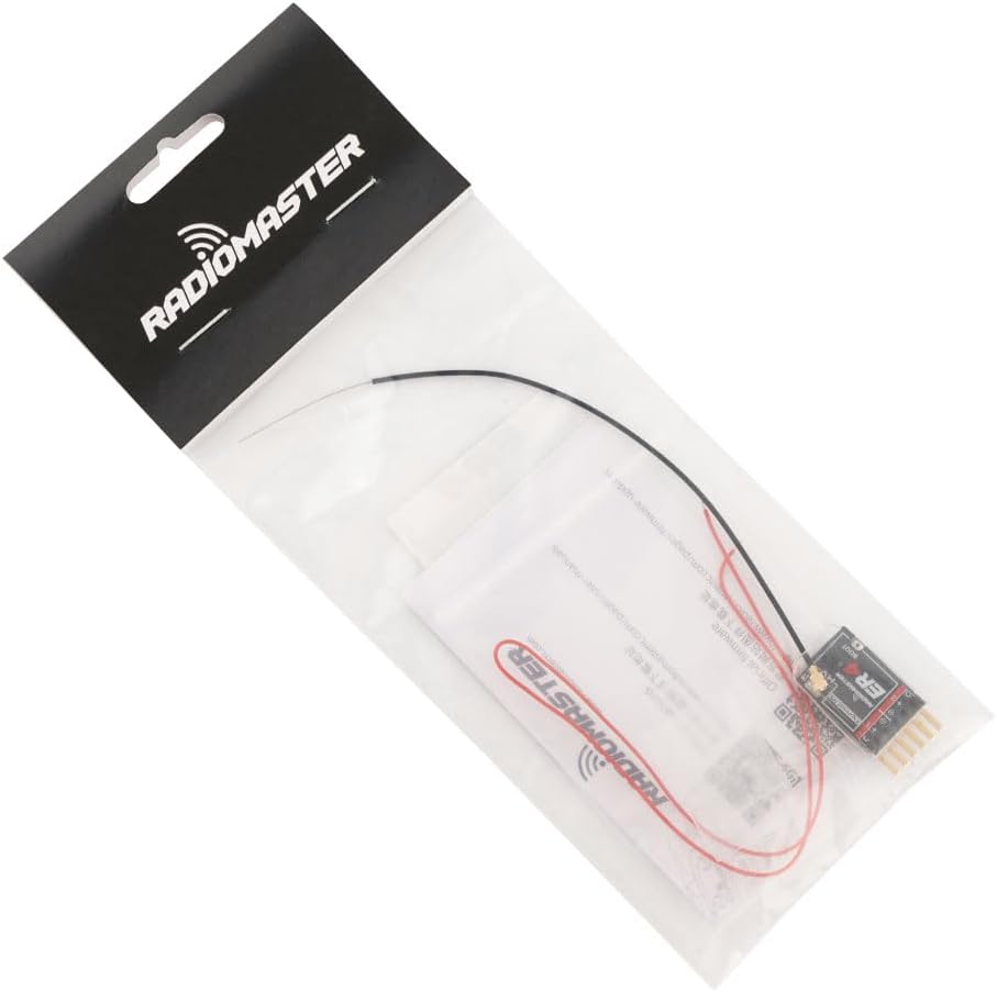
Figure 2: The Radiomaster ER4 receiver shown in its retail packaging with included wires and user card.
3. Specifications
- Model: ER4
- Frequency: 2.4GHz
- Channels: 4 PWM Channels
- Input Voltage: 4.5V - 8.4V DC
- Dimensions: 1.85 x 1.3 x 0.58 inches (approx. 30mm x 15mm x 5mm)
- Weight: Approximately 2.69 grams
- Antenna: High sensitivity 20 cm dual antenna with UFL connector
- Telemetry: Built-in receiver voltage telemetry, flight battery telemetry (with external input)
- Configuration: Wi-Fi updates and WEBUI configuration
- Interface: 4-wire CRSF interface for optional telemetry sensors

Figure 3: Detailed dimensions of the Radiomaster ER4 receiver, showing its compact size for easy integration.

Figure 4: The Radiomaster ER4 receiver displayed on a digital scale, indicating its lightweight design at approximately 2.69 grams.
4. Setup
4.1 Connecting the Receiver
The ER4 receiver features standard PWM pin headers for connecting servos and power. Ensure correct polarity when connecting power (4.5V - 8.4V DC) to the designated BAT pins.

Figure 5: Front view of the Radiomaster ER4 receiver, showing the PWM output pins (CH1-CH4) and battery input (BAT).
4.2 Antenna Installation
The ER4 receiver comes with a high sensitivity 20 cm dual antenna. It connects via a UFL connector. Ensure the antenna is securely attached and positioned for optimal signal reception.

Figure 6: Close-up view of the UFL antenna connector on the Radiomaster ER4 receiver, next to the BOOT button.
4.3 Binding Procedure (Traditional Binding)
For traditional binding, the binding phrase must be commented out in user_defines on the RX.
- Power off your transmitter.
- Plug in and unplug your receiver three times.
- Make sure the LED is doing a quick double blink, which indicates the receiver is in bind mode.
- Use the [BIND] button on the ExpressLRS Lua script, which sends out a binding pulse.
- If the receiver has a solid light, it's bound!
Video 1: This video demonstrates the binding process for Radiomaster ER series receivers, including the ER4. It shows the power cycling method and interaction with the transmitter's LUA script for successful binding.
5. Operating Modes and Features
5.1 LED Indicator Meanings
| Status Light | Meaning |
|---|---|
| Slow flash (500ms) | Waiting for transmitter |
| Fast flash (25ms) | Wi-Fi On |
| Double flash | Receiver in bind mode |
| Triple flash | Receiver functional, mode selection error |
| Solid light | Receiver functional (Connected) |
5.2 Voltage Telemetry
The ER4 receiver supports built-in receiver voltage telemetry and can also provide flight battery telemetry with automatic detection of voltage input when an external battery is connected to the EXT-V port.
5.3 Wi-Fi Update and Configuration
The receiver supports Wi-Fi updates and WEBUI configuration, ensuring your receiver is always up-to-date and easily configurable. This allows for convenient firmware upgrades and parameter adjustments.
6. Maintenance
- Keep the receiver clean and free from dust or debris.
- Regularly check all wire connections for secure fit and signs of wear.
- Ensure the antenna is not damaged and is positioned optimally for signal reception.
- Perform firmware updates via Wi-Fi as recommended by Radiomaster for optimal performance and new features.
7. Troubleshooting
- Binding Failure: Ensure your transmitter's ExpressLRS LUA script is updated and the binding phrase is correctly set or commented out on the receiver. Follow the binding procedure carefully.
- No Telemetry Data: Verify all telemetry wires are correctly connected. For external battery telemetry, ensure the battery is properly connected to the EXT-V port.
- Intermittent Signal: Check antenna placement and ensure it is not obstructed by carbon fiber or other conductive materials. Ensure the antenna is securely connected to the UFL port.
- Receiver Not Powering On: Check power connections and ensure the input voltage is within the specified 4.5V - 8.4V range.
8. Warranty and Support
For warranty claims, technical support, or further assistance, please refer to the contact information provided on the user card included in your package or visit the official Radiomaster website.


