1. Introduction
The PGMTDEFXJO XY-J02 is a versatile DC 6-30V delay timer control relay module designed for various automation applications. It features an intuitive LED display for easy configuration and monitoring, supporting multiple delay and cycle timing modes. This module can be powered via DC 6-30V or Micro USB 5V, making it suitable for a wide range of projects requiring precise time control for switching external devices.
2. Safety Information
- Always ensure proper power supply connections. Do not exceed the specified voltage range (DC 6-30V or Micro USB 5V).
- Avoid short circuits between terminals.
- Disconnect power before making any wiring changes or adjustments to the module.
- This device is not waterproof; keep it away from moisture, dust, and extreme temperatures.
- Handle with care to prevent damage to electronic components.
3. Product Features
- Wide Voltage Input: Supports DC 6-30V power supply.
- Micro USB Power: Can also be powered via Micro USB 5V for convenience.
- LED Display: Provides clear status indication and parameter viewing.
- Multiple Operating Modes: Configurable for various timing applications, including delay, cycle, and trigger modes.
- Relay Output: Controls external devices with normally open (NO), normally closed (NC), and common (COM) contacts.
- Compact Design: Small form factor for easy integration into projects.

Figure 1: Front view of the XY-J02 module, highlighting the LED display and control buttons.
4. Package Contents
- 1 x XY-J02 DC 6-30V Delay Timer Control Relay Module
5. Setup
5.1 Power Connection
The module can be powered in two ways:
- DC 6-30V Terminal: Connect your DC power supply (6V to 30V) to the '6.0-30.0V' and 'GND' screw terminals on the module. Ensure correct polarity.
- Micro USB 5V: Alternatively, connect a standard Micro USB 5V power adapter to the Micro USB port.
5.2 Load Connection
The relay output has three terminals: Normally Open (NO), Normally Closed (NC), and Common (COM). Connect your load (device to be controlled) according to your application requirements:
- Normally Open (NO): The circuit is open (disconnected) when the relay is de-energized and closes (connects) when the relay is energized.
- Normally Closed (NC): The circuit is closed (connected) when the relay is de-energized and opens (disconnects) when the relay is energized.
- Common (COM): This is the common terminal for the relay switch.
5.3 Trigger Input
If your chosen operating mode requires an external trigger, connect your trigger signal to the 'Trigger' terminal and the ground of your trigger source to the 'GND_T' terminal.
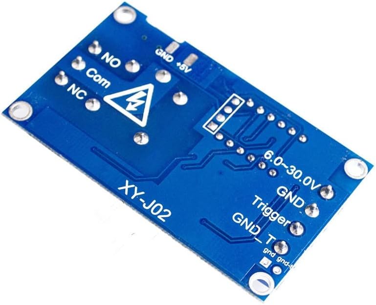
Figure 2: Back view of the XY-J02 module, illustrating the various connection terminals.
6. Operating Instructions
The XY-J02 module typically operates through a series of modes and parameter settings. While specific modes may vary, the general procedure involves selecting a mode and then setting its associated timing parameters.
6.1 Basic Display and Buttons
The module features an LED display and usually three control buttons: SET, UP, and DOWN (or similar labels like STOP).
- SET Button: Used to enter/exit programming mode and confirm parameter changes.
- UP Button: Used to increase values or navigate through options.
- DOWN/STOP Button: Used to decrease values, navigate through options, or stop the current operation.
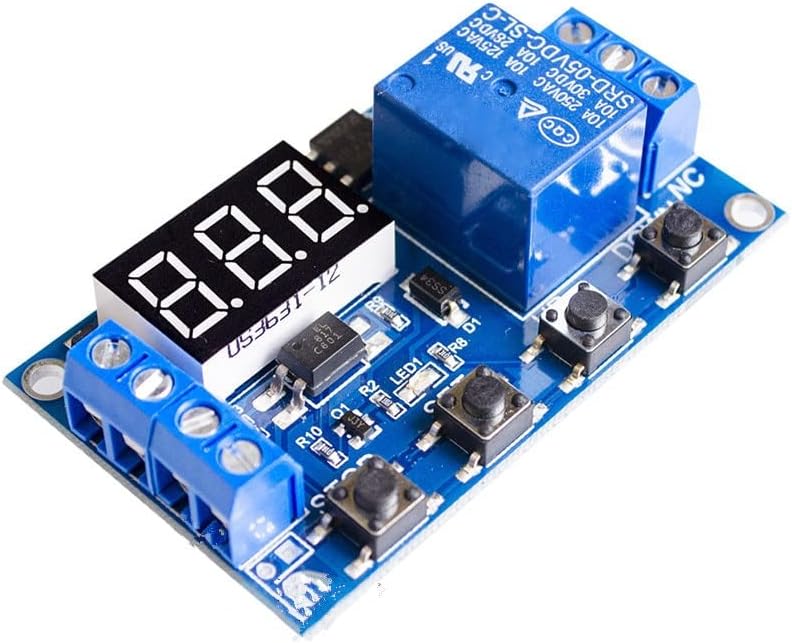
Figure 3: Top view of the XY-J02 module, showing the LED display and control buttons.
6.2 Mode Selection and Parameter Setting (General Guide)
- Enter Programming Mode: Press and hold the SET button for a few seconds until the display shows a mode code (e.g., P1.1, P1.2, P2, P3, P4).
- Select Mode: Use the UP and DOWN buttons to cycle through the available operating modes. Common modes include:
- P1.1: Trigger delay ON (relay closes after delay, then opens).
- P1.2: Trigger delay OFF (relay opens after delay, then closes).
- P1.3: Trigger cycle (relay cycles ON/OFF for a set number of times after trigger).
- P2: Fixed time delay (relay closes for a set time, then opens).
- P3: Cycle timing (relay continuously cycles ON/OFF).
- Set Parameters: Once a mode is selected, press SET briefly to enter parameter setting for that mode. The display will show parameters like OP (ON time), CL (OFF time), LOP (cycle count). Use UP and DOWN to adjust values.
- Select Time Unit: While setting a parameter, press the SET button again briefly to cycle through time units (e.g., seconds, minutes, hours, milliseconds). A decimal point on the display often indicates the unit (e.g., no decimal for seconds, one decimal for 0.1 seconds, two decimals for 0.01 seconds).
- Save Settings: After setting all parameters for the chosen mode, press and hold the SET button until the display returns to the normal operating state. This saves the configuration.
- Start/Stop: In normal operating mode, a short press of the DOWN/STOP button may toggle the relay ON/OFF or start/stop the timer depending on the mode.
7. Maintenance
- Keep the module clean and dry. Use a soft, dry cloth to remove dust.
- Periodically inspect all wiring connections to ensure they are secure and free from corrosion.
- Avoid exposing the module to strong vibrations or mechanical shocks.
8. Troubleshooting
| Problem | Possible Cause | Solution |
|---|---|---|
| Module does not power on | Incorrect power connection; Power supply failure; Voltage out of range. | Check power wiring polarity and connection. Verify power supply output voltage (6-30V DC or 5V Micro USB). |
| Relay not activating/deactivating | Incorrect wiring to load; Incorrect operating mode selected; Trigger signal issue; Faulty relay. | Verify load wiring (NO/NC/COM). Check selected operating mode and parameters. Ensure trigger signal is correct if applicable. Test relay functionality. |
| Timing is inaccurate | Incorrect time unit selected; Parameter values set incorrectly. | Re-enter programming mode and verify the time unit (seconds, minutes, hours) for OP/CL parameters. Double-check the set time values. |
| Display shows error code | Internal error or specific condition. | Refer to specific error codes if available in detailed product documentation. Try power cycling the module. |
9. Specifications
| Feature | Specification |
|---|---|
| Model | XY-J02 |
| Input Voltage | DC 6-30V (Terminal), Micro USB 5V |
| Output Type | Relay Output (NO, NC, COM) |
| Relay Contact Rating | 10A 250VAC / 10A 30VDC (Typical, refer to relay component for exact rating) |
| Display | LED Digital Display |
| Dimensions (L x W x H) | 1.18 x 0.79 x 0.39 inches |
| Item Weight | 1.76 ounces |
| Manufacturer | PGMTDEFXJO |
10. Warranty and Support
For warranty information, technical assistance, or further inquiries regarding your PGMTDEFXJO XY-J02 module, please refer to the seller's policies or contact PGMTDEFXJO directly through their official support channels. Keep your purchase receipt for warranty claims.