Introduction
The NICGIGA CPE-S900 Outdoor Wireless Bridge is designed to provide reliable, long-distance wireless network connectivity for various outdoor applications. This 5.8G point-to-point wireless Ethernet bridge router offers high-speed data transmission and is pre-configured for easy plug-and-play setup, making it ideal for extending networks to remote buildings, surveillance systems, or other distant locations.

Image: Two NICGIGA CPE-S900 Outdoor Wireless Bridge units, showcasing their sleek, white design.

Image: Various application scenarios for the wireless bridge, including community monitoring, parking lots, warehouses, and shipside environments.
Package Contents
Please verify that all items are present in the package:
- 2 x NICGIGA Outdoor Wireless Bridge (CPE-S900)
- 2 x Passive 24V PoE Power Adapter
Key Features
- Ultra-Long-Distance Transmission: Achieves up to 4KM wireless WiFi transmission with 866Mbps speed.
- Plug and Play Setup: Factory default pairing allows for immediate use without complex GUI configurations.
- 5.8G Frequency Band: Utilizes the 5.8GHz band to minimize interference from common 2.4GHz household devices.
- Flexible Networking: Supports both point-to-point and point-to-multipoint configurations.
- Dual Power Modes: Compatible with standard power adapters and Passive 24V PoE, enabling power supply over Ethernet cables up to 70 meters.
- Professional Outdoor Design: Built to withstand harsh environments with IP65 waterproof rating, high/low temperature resistance, dustproof properties, and lightning protection.
- Gigabit RJ45 Ports: Equipped with two Gigabit RJ45 LAN ports for high-speed wired connections.

Image: Illustration of the 4KM ultra-long-distance transmission capability between two wireless bridge units.
Setup Guide
1. Pre-installation Considerations
- Line of Sight: Ensure a clear line of sight between the two wireless bridge units for optimal performance. Obstructions like trees or buildings can significantly degrade signal quality.
- Power Source: Plan for power adapter or PoE (Power over Ethernet) availability at both installation points.
2. Easy Pairing (Factory Default)
The CPE-S900 units come factory-paired, simplifying the setup process. No complex GUI configuration is required for basic point-to-point operation.

Image: Visual guide to the easy pairing process using the digital tube display and A-B button on the units.
3. Connection Diagram
Follow the diagram below for typical Master and Slave CPE connections:

Image: A detailed connection diagram illustrating how to set up the Master and Slave CPE units with a router and client devices, utilizing PoE adapters.
- Connect the Master CPE to your main network router using an Ethernet cable. Power the Master CPE via its PoE adapter.
- Connect the Slave CPE to your desired network device (e.g., another router, switch, computer, or surveillance monitor) using an Ethernet cable. Power the Slave CPE via its PoE adapter.
- Ensure both units are powered on and aligned for optimal signal strength.
4. Mounting
The units are designed for pole installation using stainless steel rolling strips (not included). Ensure secure mounting to prevent movement due to wind or other environmental factors.

Image: Visual representation of simple installation steps, including pole mounting, using the built-in signal indicator, and the benefit of factory default pairing.
Operation
Signal Indicators
Each unit features a built-in signal indicator to help you find the optimal placement position and ensure a strong connection. The indicator lights provide real-time feedback on signal strength.
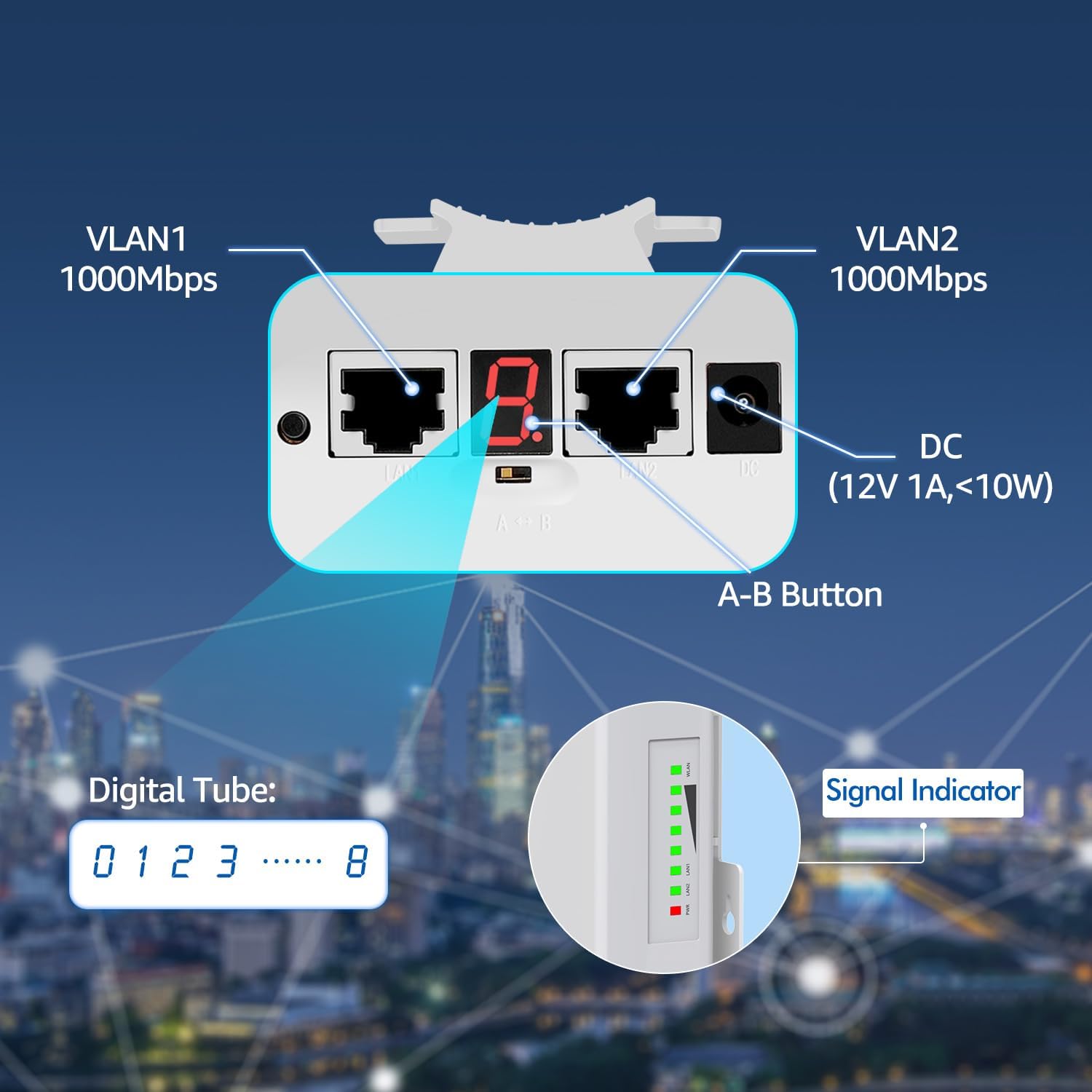
Image: A close-up view of the CPE-S900 unit, highlighting its Gigabit LAN ports, DC power input, A-B button, digital tube display, and signal indicator lights.
Power Supply Modes
The CPE-S900 supports two power supply methods:
- Power Adapter: Use the provided 12V DC power adapter.
- Passive 24V PoE: Power the device directly through the Ethernet cable using the included Passive 24V PoE injector. This allows for flexible deployment up to 70 meters from the power source.
Maintenance and Durability
The NICGIGA CPE-S900 is engineered for professional outdoor use, designed to withstand various harsh environmental conditions. Its robust construction ensures long-term reliability.
- IP65 Waterproof: Protects against dust ingress and low-pressure water jets from any direction.
- Temperature Resistance: Operates reliably across a wide range of temperatures, from extreme cold to high heat.
- Dustproof: Sealed design prevents dust and debris from affecting internal components.
- Lightning Protection: Incorporates features to protect against electrical surges caused by lightning.
- Anti-aging Materials: Constructed with durable materials to resist degradation from prolonged exposure to sunlight and weather.

Image: Icons illustrating the professional outdoor design features: IP65 waterproof, low temperature resistance, lightning protection, and high temperature resistance.
Troubleshooting
- No Connection:
- Ensure both units are powered on and their signal indicators are active.
- Verify clear line of sight between the units. Any new obstructions (e.g., growing trees, new buildings) can block the signal.
- Check Ethernet cable connections at both ends of each unit and to the router/device.
- Confirm the PoE adapters are correctly connected and providing power.
- Re-align the units slightly to optimize signal strength, observing the signal indicator lights.
- Slow Speed:
- Check the signal indicator lights; a weaker signal will result in lower speeds.
- Ensure there are no new sources of 5.8GHz interference in the area.
- Verify the bandwidth of your main internet connection. The wireless bridge cannot exceed the speed of the source.
- Ensure the Ethernet cables used are Gigabit-rated (Cat5e or Cat6) for optimal performance.
- Intermittent Connection:
- This can be caused by environmental factors like heavy rain, snow, or dense fog, which can temporarily attenuate the signal.
- Check for physical movement of the units due to wind or improper mounting.
- Ensure power supply is stable and not fluctuating.
- Units Not Pairing (if factory pairing fails):
- While units are factory-paired, if issues arise, consult the full manual for advanced pairing procedures or contact support.
Technical Specifications
| Feature | Specification |
|---|---|
| Model Number | CPE-S900 |
| Wireless Communication Standard | 802.11a |
| Frequency Band Class | Single-Band (5.8 GHz) |
| Transmission Distance | Up to 4KM (2.5 miles) |
| Wireless Speed | 866Mbps |
| LAN Ports | 2 x Gigabit RJ45 |
| Power Supply | Passive 24V PoE, 12V DC |
| Special Feature | Weatherproof (IP65), High/Low Temperature Resistance, Lightning Protection |
| Item Weight | 2.71 pounds (per pair) |
| Package Dimensions | 13.66 x 5.04 x 4.09 inches |
| Recommended Uses | Business, Outdoor Surveillance, Remote Network Extension |

Image: Actual speed measurement results for 4KM transmission, detailing various signal parameters and achieved speeds.

Image: Actual speed measurement results for 1.5KM transmission, detailing various signal parameters and achieved speeds.
Warranty and Support
Every NICGIGA Wireless Bridge undergoes rigorous testing to ensure reliability, quality, and performance. NICGIGA provides lifetime technical support for this product. For assistance, please contact NICGIGA customer service through the vendor's official channels.


