1. Introduction
This manual provides detailed instructions for assembling, operating, and maintaining your THEPHAMVX At89C2051 Electronic Clock DIY Kit. This kit is designed for enthusiasts to build a functional digital clock with an LED display, powered by a DC 9V-12V supply.
Before beginning assembly, please read all instructions carefully and ensure you have the necessary tools and a suitable workspace.
2. Safety Precautions
- Always work in a well-ventilated area when soldering.
- Use appropriate safety gear, including safety glasses, to protect your eyes from solder splatter.
- Ensure your soldering iron is properly grounded and handle it with care to avoid burns.
- Keep electronic components away from children and pets.
- Verify component polarity (e.g., diodes, electrolytic capacitors, ICs) before soldering to prevent damage.
- Double-check all connections before applying power to the circuit.
3. Package Contents
Please verify that all components listed below are present in your kit before starting assembly.
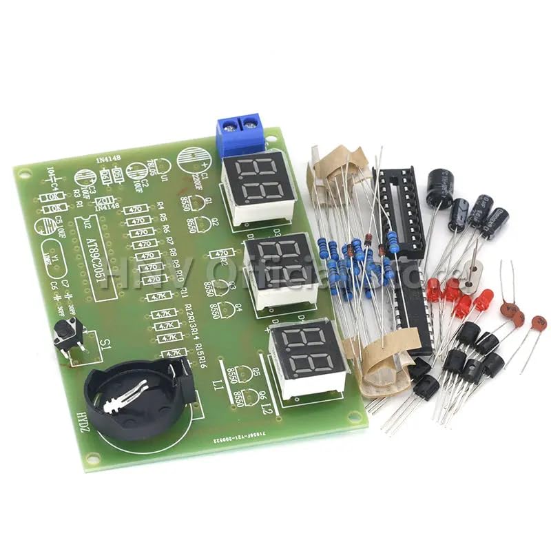
Image 1: All components of the At89C2051 Electronic Clock DIY Kit laid out, including the PCB, resistors, capacitors, diodes, transistors, IC socket, LED displays, push button, crystal oscillator, battery holder, and power connector.
- Printed Circuit Board (PCB)
- At89C2051 Microcontroller IC
- IC Socket (DIP-20)
- Digital Tube LED Displays (3 units)
- Resistors (various values)
- Capacitors (electrolytic and ceramic, various values)
- Diodes (e.g., 1N4148)
- Transistors (e.g., 8550)
- Crystal Oscillator (e.g., 12MHz)
- Push Button Switch
- Battery Holder (for CR2032 or similar, for backup)
- DC Power Jack/Terminal Block
- LEDs (indicator lights)
4. Setup and Assembly Instructions
Follow these steps carefully to assemble your electronic clock kit. It is recommended to solder components from lowest height to highest height.
4.1 Tools Required
- Soldering Iron (25-40W recommended)
- Solder wire (thin gauge, rosin core)
- Solder wick or desoldering pump (for corrections)
- Wire cutters/flush cutters
- Needle-nose pliers
- Multimeter (optional, for testing)
4.2 Assembly Steps
- Resistors: Identify all resistors by their color codes or marked values. Bend their leads, insert them into their designated positions on the PCB (marked R1, R2, etc.), and solder them. Trim excess leads. Resistors are non-polarized.
- Diodes: Identify the 1N4148 diodes. Note the black band on one end of the diode, which indicates the cathode. Match this band with the corresponding marking on the PCB. Insert and solder.
- Ceramic Capacitors: These are typically small, non-polarized components. Insert them into their designated positions (e.g., C5, C6, C7) and solder.
- Electrolytic Capacitors: These are polarized. The longer lead is positive (+), and the shorter lead is negative (-). The negative side is also often marked with a stripe on the capacitor body. Match the polarity with the markings on the PCB. Insert and solder.
- Transistors: Identify the 8550 transistors. Match the flat side of the transistor with the flat side marking on the PCB. Insert and solder.
- IC Socket: Insert the 20-pin IC socket into its designated position (U1). Ensure the notch on the socket aligns with the notch marking on the PCB. Solder all pins. This allows for easy replacement of the microcontroller if needed.
- Crystal Oscillator: Insert the crystal oscillator (e.g., 12MHz) into its designated position (Y1). It is non-polarized. Solder its two leads.
- LEDs (Indicator Lights): These are polarized. The longer lead is positive (+), and the shorter lead is negative (-). Match the polarity with the PCB markings. Insert and solder.
- Push Button Switch: Insert the small push button switch (S1) into its designated position. Solder its leads.
- Digital Tube LED Displays: Carefully insert the three digital tube LED displays (D1, D2, D3) into their respective positions. Ensure they are flush with the PCB and solder all pins.
- Battery Holder: Insert the CR2032 battery holder into its position. Ensure correct polarity if applicable (usually marked). Solder its connection points.
- DC Power Terminal Block: Insert the terminal block for power input (VCC) into its designated spot. Solder its pins.
- Microcontroller IC (At89C2051): After all other components are soldered, carefully insert the At89C2051 IC into the IC socket. Ensure the notch on the IC aligns with the notch on the socket and the PCB. Gently press down until all pins are seated.
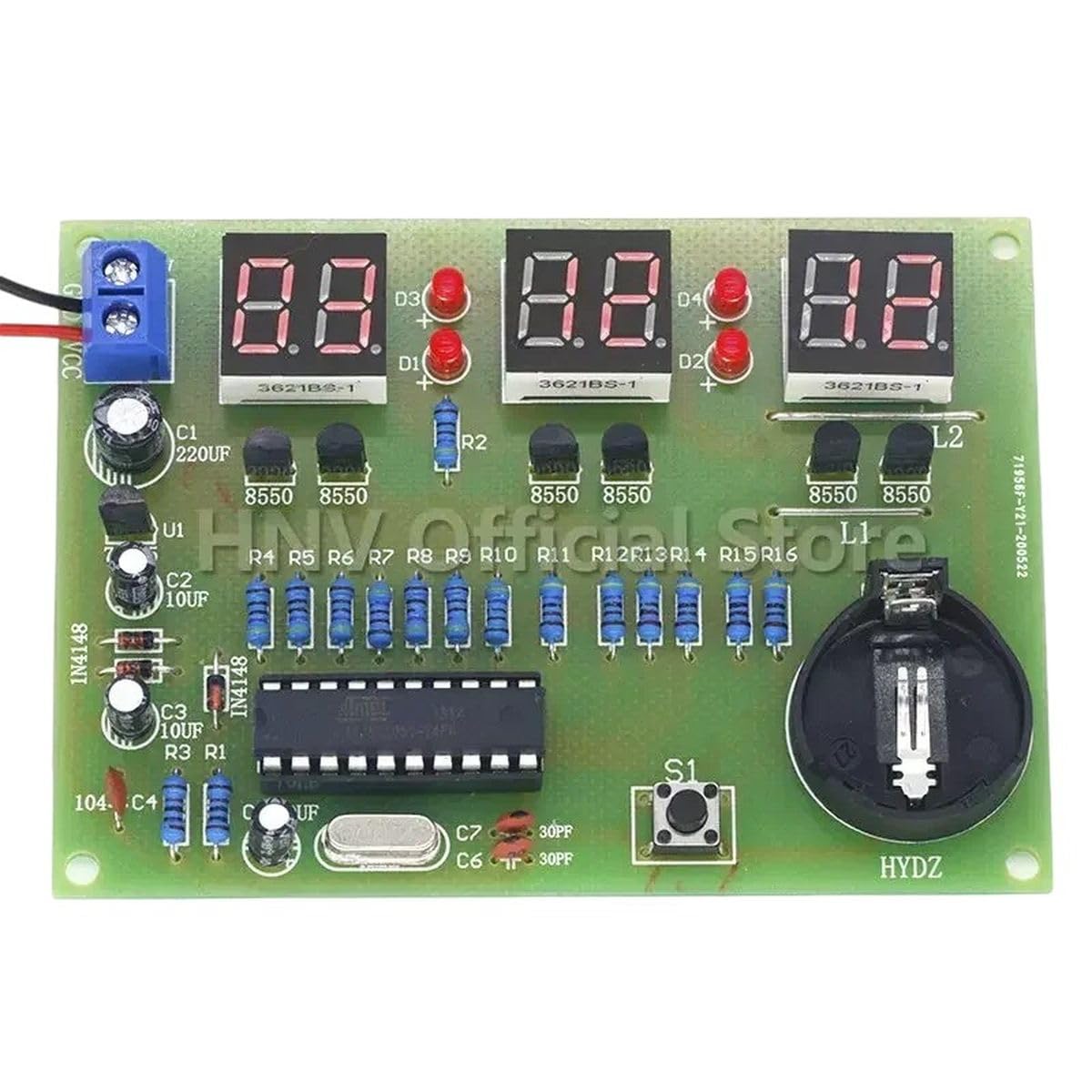
Image 2: The fully assembled At89C2051 Electronic Clock circuit board, showing all components soldered in place and the digital LED displays illuminated.
5. Operating Instructions
5.1 Powering On
Connect a DC 9V-12V power supply to the terminal block. Ensure correct polarity (+ to VCC, - to GND). The digital LED displays should illuminate, showing the current time.
5.2 Setting the Time
The kit typically includes a single push button (S1) for time adjustment. The exact operation may vary slightly based on the firmware, but common methods include:
- Short Press: To switch between displaying hours and minutes, or to increment a value.
- Long Press: To enter time setting mode (e.g., hours flashing), then short press to adjust hours. Another long press might switch to minutes setting mode, then short press to adjust minutes.
- Refer to the specific programming of your At89C2051 chip for precise button functionality.
Insert a CR2032 battery into the battery holder for time backup in case of power loss.
6. Maintenance
- Keep the circuit board clean and free from dust. Use a soft brush if necessary.
- Avoid exposing the circuit to moisture or extreme temperatures.
- If the clock loses time frequently, check the power supply stability and the CR2032 backup battery. Replace the battery if it is depleted.
- Periodically inspect solder joints for any signs of cracking or corrosion. Re-solder if needed.
7. Troubleshooting
| Problem | Possible Cause | Solution |
|---|---|---|
| Clock does not power on / Displays are blank. |
|
|
| Incorrect time displayed or time drifts. |
|
|
| One or more LED segments are not lighting up. |
|
|
8. Specifications
- Model: At89C2051 Electronic Clock DIY Kit
- Input Voltage: DC 9V - 12V
- Microcontroller: Atmel At89C2051
- Display Type: 3-digit 7-segment LED display
- Timekeeping: Real-time clock functionality with backup battery support (CR2032, not always included)
- Functions: Time display, time setting


