
1. Introduction
This manual provides detailed instructions for the installation, operation, and maintenance of your GOOD STORY WB501C 5.8GHz Outdoor Wireless Bridge. This device is designed to establish a stable and high-speed wireless network connection over long distances, functioning as a virtual network cable.
The wireless bridge transmits network signals wirelessly through the air using 5.8GHz wireless communication technology. It supports both point-to-point (PTP) and point-to-multipoint (PTMP) connections, making it suitable for extending network coverage to outbuildings, enhancing security systems, and supporting IoT devices.
2. Package Contents
Verify that all items listed below are present in your package. If any items are missing or damaged, please contact customer support.
- Wireless Bridge Units (2 or 3, depending on package)
- PoE Adapters
- Ethernet Cables
- Mounting Straps/Clamps

3. Product Overview
The WB501C Wireless Bridge units are designed for outdoor use, featuring a robust, weatherproof casing. Each unit includes multiple ports and indicators for easy setup and monitoring.
3.1. Ports and Indicators
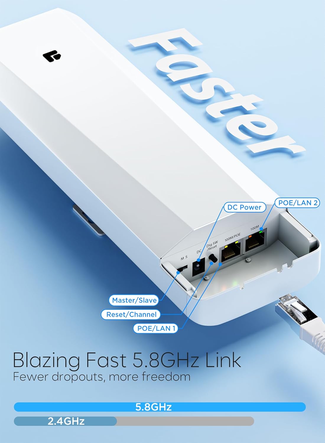
- DC Power: Input for direct current power supply.
- POE/LAN 1: Power over Ethernet (PoE) input and Local Area Network (LAN) port for connecting to your network device (e.g., router, switch). This port also supplies power to the unit via the PoE adapter.
- POE/LAN 2: Secondary LAN port, also capable of PoE output for powering another device or acting as a data passthrough.
- Master/Slave Switch: Used to designate the unit as either a Master or a Slave in a wireless bridge setup.
- Reset/Channel Button: Used to reset the device to factory defaults or change the wireless channel.
- LED Indicators: A series of LEDs on the side of the unit indicate power status, network activity, and signal strength.
4. Setup Instructions
4.1. Pre-Configuration
The GOOD STORY WB501C Wireless Bridge units are pre-configured for ease of installation. This means the Master and Slave units are already paired and ready for deployment. No complex software setup is required for basic point-to-point operation.

4.2. Important Power Information
WARNING: The WB501C Wireless Bridge units operate on 24V DC Power over Ethernet (PoE). You MUST use the PoE adapters provided with the kit. Connecting these units to standard 48V PoE switches or injectors will cause irreversible damage to the devices.
4.3. Physical Installation and Connection
- Identify Master and Slave Units: One unit will be designated as 'Master' and the other as 'Slave' (or multiple Slaves for PTMP). Ensure the Master/Slave switch on each unit is set correctly.
- Mounting: Securely mount the wireless bridge units in their desired outdoor locations using the provided mounting straps/clamps. Ensure a clear line of sight between the Master and Slave units for optimal performance. Avoid obstructions like trees or buildings.
- Connect Master Unit:
- Connect an Ethernet cable from your main router or network switch to the LAN port of the Master unit's PoE adapter.
- Connect another Ethernet cable from the PoE port of the Master unit's PoE adapter to the POE/LAN 1 port on the Master wireless bridge unit.
- Plug the PoE adapter into a power outlet.
- Connect Slave Unit(s):
- Connect an Ethernet cable from the POE/LAN 1 port on the Slave wireless bridge unit to the PoE port of the Slave unit's PoE adapter.
- Connect another Ethernet cable from the LAN port of the Slave unit's PoE adapter to your client device (e.g., computer, secondary router/WAP, NVR).
- Plug the Slave unit's PoE adapter into a power outlet.
- Power On: Once all connections are secure, power on both PoE adapters. The units should power up and establish a wireless link automatically.


4.4. Video Guide: Pre-Programmed Set
This video demonstrates the pre-programmed setup process, showing how the units are ready for deployment right out of the box.
5. Operating Instructions
5.1. Point-to-Point (PTP) Operation
In a PTP setup, two wireless bridge units (one Master, one Slave) establish a dedicated wireless link. This link acts as a transparent Ethernet cable, extending your network from one location to another. Once connected, any device plugged into the Slave unit's LAN port will have network access as if it were directly connected to the Master's network.
5.2. Point-to-Multipoint (PTMP) Operation
For PTMP setups, one Master unit can connect to up to eight Slave units. This allows for network extension to multiple remote locations from a single central point. Each Slave unit will provide network access to its connected devices.
5.3. Signal Strength Indicators
Monitor the LED indicators on the side of the units to assess signal strength. A higher number of illuminated LEDs indicates a stronger and more stable wireless link. Adjust the alignment of the units if signal strength is low.
6. Applications
The GOOD STORY WB501C Wireless Bridge offers versatile solutions for various network extension needs:
- Home Network Expansion: Extend internet access to detached garages, barns, guest houses, or other outbuildings on your property.
- Business Connectivity: Establish network links between different buildings in an office park or campus.
- Security Camera Systems: Provide reliable network connectivity for IP cameras and Network Video Recorders (NVRs) in remote locations.
- Starlink Integration: Extend your Starlink internet connection to other parts of your property.
- IoT and Smart Home Devices: Ensure seamless connectivity for smart devices in areas with limited wired infrastructure.


7. Maintenance
The WB501C Wireless Bridge is designed for robust outdoor performance with an IP65 rating, making it resistant to dust and water. To ensure optimal longevity and performance:
- Regular Inspection: Periodically check the mounting hardware and cables for any signs of wear, corrosion, or damage.
- Clear Line of Sight: Ensure that no new obstructions (e.g., growing trees, new structures) have appeared that could block the line of sight between units.
- Cleaning: Gently clean the exterior of the units with a soft, damp cloth if dirt or debris accumulates. Do not use harsh chemicals or abrasive materials.

7.1. Video Guide: Weatherproof Wireless Bridge for Outdoor
This video highlights the weatherproof features of the wireless bridge, demonstrating its durability in various outdoor conditions.
8. Troubleshooting
- No Power: Ensure the PoE adapters are correctly connected to both the power outlet and the wireless bridge unit's POE/LAN 1 port. Verify the power outlet is functional.
- No Link/Poor Signal:
- Check for a clear line of sight between the Master and Slave units. Any obstructions can severely degrade performance.
- Ensure units are properly aligned. Slight adjustments can significantly improve signal strength.
- Verify the Master/Slave switch is correctly set on each unit.
- Check the signal strength LEDs on the units. If they are low, re-align or check for obstructions.
- Network Connectivity Issues:
- Confirm all Ethernet cables are securely connected and undamaged.
- Ensure your main router/network is functioning correctly.
- If using a secondary router/WAP at the Slave end, ensure it is configured correctly to receive internet from the bridge.
- Device Damage from Incorrect Power: As noted in Section 4.2, using non-24V PoE power sources will damage the units. This damage is not covered under warranty. Always use the provided PoE adapters.
- Resetting to Factory Defaults: If experiencing persistent issues, press and hold the Reset/Channel button for approximately 10 seconds until the LEDs flash, then release. This will restore the unit to its original factory settings. You may need to re-establish the Master/Slave configuration if it was manually changed.
9. Specifications
| Feature | Detail |
|---|---|
| Model Number | WB501C |
| Frequency Band Class | Single-Band (5.8GHz) |
| Wireless Communication Standard | 802.11n |
| Connectivity Technology | Wi-Fi |
| Special Features | Internet Security, LED Indicator, Weatherproof (IP65) |
| Recommended Uses | Business, Residential |
| Compatible Devices | Laptop, Personal Computer, Security Camera, Smart Television |
| Power Input | 24V DC PoE (via included PoE adapter) |
| Item Weight | 2.59 pounds (per unit, approximate) |
| Package Dimensions | 12.71 x 7.52 x 2.83 inches (approximate) |
10. Warranty and Support
GOOD STORY products are designed for reliability and performance. For specific warranty details, please refer to the warranty card included with your product or contact your retailer. Our expert team is available to provide support and assist with any custom configurations or technical inquiries you may have.
For assistance, please visit the GOOD STORY Store on Amazon or contact our customer service.