1. Introduction
This manual provides detailed instructions for the UeeKKoo 1.83inch Round LCD Display Module. This module features a 240x280 resolution, 65K colors, and an IPS display panel, offering clear and vibrant visuals. It is designed with an embedded NV3030B driver chip and utilizes a 4-wire SPI interface, minimizing required IO pins. The module is compatible with various development boards, including Raspberry Pi, Arduino, STM32, and ESP32.
Key features include:
- 1.83inch LCD Display Module with 240x280 Resolution and 65K colors.
- Embedded NV3030B driver chip for efficient display control.
- SPI interface for simplified connectivity and reduced GPIO usage.
- Compatible with Raspberry Pi, Arduino, STM32, and ESP32.
- Operates on 3.3V / 5V power supply.
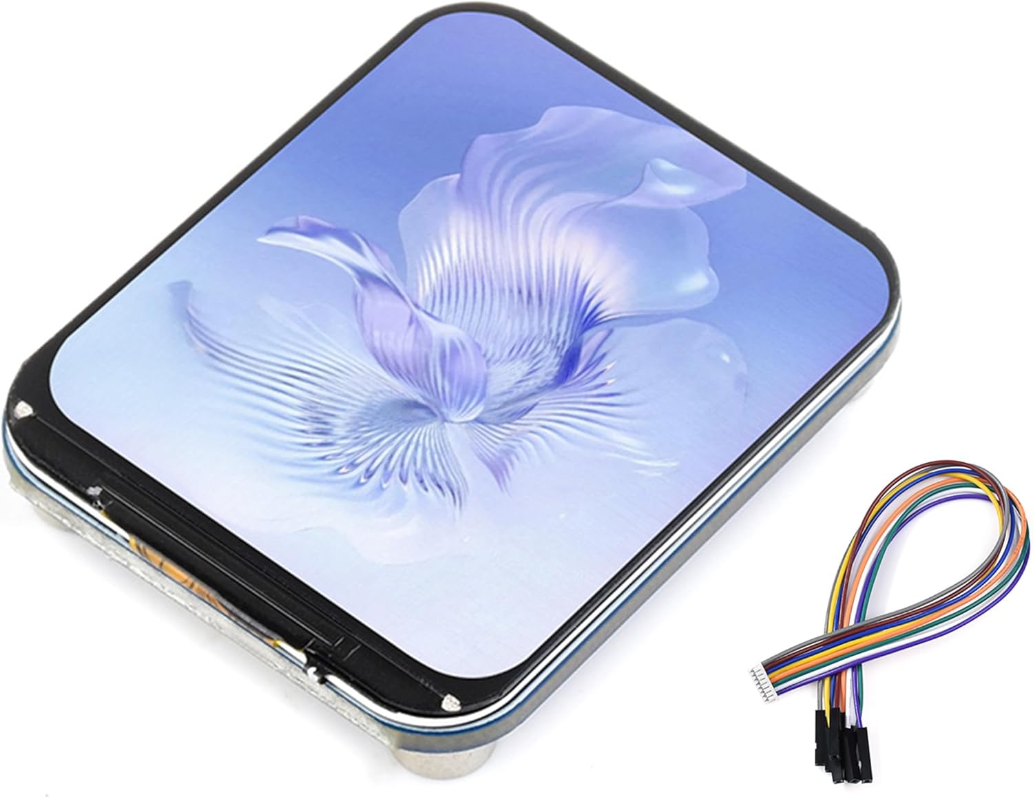
Figure 1: UeeKKoo 1.83inch Round LCD Display Module with included GH1.25 8-PIN cable.

Figure 2: Overview of the 1.83inch LCD Display Module's key specifications including size, resolution, display color, panel type, driver, and interface.
2. Specifications
| Feature | Description |
|---|---|
| Operating Voltage | 3.3V / 5V |
| Resolution | 240 × 280 pixels |
| Display Panel | IPS |
| Driver Chip | NV3030B |
| Communication Interface | 4-wire SPI |
| Display Size | 30.20 × 35.23mm |
| Pixel Size | 0.126 × 0.126mm |
| Module Size | 33.00 × 40.00mm |
| Compatible Devices | Raspberry Pi, Arduino, STM32, ESP32 |

Figure 3: Detailed outline dimensions of the module in millimeters and an example of its integration with a development board.
3. Package Content
The package includes the following items:
- 1.83inch LCD Module x1
- GH1.25 8-PIN cable (~20cm) x1
4. Setup and Hardware Connection
This section details the pin definitions and connection methods for various development boards. The module communicates via a 4-wire SPI interface.
4.1 Pin Definitions

Figure 4: Pinout diagram of the 1.83inch LCD module's onboard SPI control interface.
| Pin | Function |
|---|---|
| VCC | Power input (3.3V / 5V) |
| GND | Ground |
| DIN | SPI data input |
| CLK | SPI clock input |
| CS | Chip selection (low active) |
| DC | Data/Command selection (high for data, low for command) |
| RST | Reset (low active) |
| BL | Backlight control |
4.2 Raspberry Pi Hardware Connection
Connect the LCD to your Raspberry Pi using the 8-PIN cable according to the table below. Use the pin header or PH2.0 8PIN interface. The wire colors in the diagram are for reference only; actual colors may vary.
| LCD | BCM2835 | Board |
|---|---|---|
| VCC | 3.3V | 3.3V |
| GND | GND | GND |
| DIN | MOSI | 19 |
| CLK | SCLK | 23 |
| CS | CE0 | 24 |
| DC | 25 | 22 |
| RST | 27 | 13 |
| BL | 18 | 12 |

Figure 5: Wiring diagram showing the connection of the LCD module to a Raspberry Pi board.
4.3 Raspberry Pi Pico Hardware Connection
The provided example is based on the Raspberry Pi Pico. If necessary, port the demo according to the actual pinout.
| LCD | Pico |
|---|---|
| VCC | 3.3V |
| GND | GND |
| DIN | GP11 |
| CLK | GP10 |
| CS | GP9 |
| DC | GP8 |
| RST | GP12 |
| BL | GP13 |

Figure 6: Wiring diagram showing the connection of the LCD module to a Raspberry Pi Pico board.
4.4 ESP32 Hardware Connection
The provided example is based on the ESP32-S3 development board. If necessary, port the demo according to the actual pinout.
| LCD | ESP32 |
|---|---|
| VCC | 3V3 |
| GND | GND |
| DIN | IO11 |
| CLK | IO12 |
| CS | IO10 |
| DC | IO46 |
| RST | IO3 |
| BL | IO8 |

Figure 7: Wiring diagram showing the connection of the LCD module to an ESP32 development board.
4.5 STM32 Hardware Connection
The provided example is based on the XNUCLEO-F103RB development board. If necessary, port the demo according to the actual pinout.
| LCD | STM32 |
|---|---|
| VCC | 3.3V |
| GND | GND |
| DIN | PA7 |
| CLK | PA5 |
| CS | PB6 |
| DC | PA8 |
| RST | PA9 |
| BL | PC7 |

Figure 8: Wiring diagram showing the connection of the LCD module to an STM32 development board.
4.6 Arduino Hardware Connection
The provided example is based on the ATmega328P development board (Arduino UNO R3). If necessary, port the program according to the actual pinout.
| LCD | UNO |
|---|---|
| VCC | 5V |
| GND | GND |
| DIN | D11 |
| CLK | D13 |
| CS | D10 |
| DC | D7 |
| RST | D8 |
| BL | D9 |

Figure 9: Wiring diagram showing the connection of the LCD module to an Arduino UNO board.
5. Operating Instructions
Once the hardware connections are established, the LCD module requires programming to display content. The module supports 8-bit, 9-bit, 16-bit, and 18-bit color formats (RGB444, RGB565, RGB666). The example programs typically use the RGB565 format.
For detailed programming examples and libraries compatible with Raspberry Pi, Arduino, STM32, and ESP32, please refer to the official online development resources provided by the manufacturer. These resources include code examples and necessary drivers to initialize and control the display.
Online Development Resources: bit.ly/44Lm7At
Follow the instructions within the development resources to compile and upload the appropriate code to your chosen development board. This will enable the LCD to display graphics and text.
6. Maintenance
To ensure the longevity and optimal performance of your 1.83inch Round LCD Display Module, observe the following maintenance guidelines:
- Handling: Handle the module by its edges to avoid touching the display surface or electronic components. Static electricity can damage sensitive components.
- Cleaning: Use a soft, lint-free cloth, slightly dampened with water or a mild, non-abrasive screen cleaner, to gently wipe the display surface. Avoid harsh chemicals, solvents, or abrasive materials.
- Storage: Store the module in a dry, dust-free environment, away from direct sunlight and extreme temperatures.
- Power Supply: Always ensure the correct operating voltage (3.3V / 5V) is supplied. Incorrect voltage can cause irreversible damage.
- Connections: Periodically check all cable connections to ensure they are secure and free from corrosion.
7. Troubleshooting
If you encounter issues with your LCD module, consider the following troubleshooting steps:
- No Display/Blank Screen:
- Verify all power connections (VCC, GND) are correctly wired and receiving the appropriate voltage (3.3V or 5V).
- Check all SPI communication lines (DIN, CLK, CS, DC, RST) for correct wiring and secure connections.
- Ensure the backlight (BL) pin is correctly connected and receiving power if you are controlling it.
- Confirm that your code is correctly initializing the NV3030B driver chip and sending display data.
- Garbled or Incorrect Display:
- Double-check the SPI pin assignments in your code against the hardware connection table for your specific development board.
- Ensure the correct color format (e.g., RGB565) is being used in your software.
- Verify that the data transmission rate (SPI clock speed) is compatible with the module and your development board.
- Check for any loose connections or damaged wires in the SPI bus.
- Module Not Responding:
- Ensure the RST pin is correctly toggled during initialization (typically pulled low then high).
- Confirm that the CS (Chip Select) pin is correctly managed by your software, being pulled low during communication and high when idle.
- Test with a known-good example program from the online development resources to rule out software issues.
- Physical Damage:
- Inspect the module for any visible physical damage, such as cracked screen, bent pins, or burnt components.
If problems persist after following these steps, consult the online development resources or seek assistance from the manufacturer's support channels.
8. Warranty and Support
This UeeKKoo product is covered by a standard manufacturer's warranty against defects in materials and workmanship. Please retain your proof of purchase for warranty claims.
For technical support, additional resources, or warranty inquiries, please visit the UeeKKoo official store on Amazon or refer to the online development resources link provided in Section 5.
UeeKKoo Amazon Store: https://www.amazon.com/stores/UeeKKoo/page/E9C7F254-4011-4DC1-8B2A-35996705C960


