1. Introduction
The MYPIN Fingerprint Remote Control Cabinet Lock (Model HS0433) provides a secure and convenient solution for protecting your belongings in cabinets, drawers, and wardrobes. This advanced lock features multiple unlocking methods, including fingerprint recognition, remote control, and an emergency USB key. Designed for hole-less installation, it preserves the integrity of your furniture while offering robust security.

Image: Overview of the MYPIN Fingerprint Remote Control Cabinet Lock highlighting fingerprint unlock, remote control, USB-C key, long battery life, low battery reminder, emergency charging, smart chip, multiple scenarios, automatic lock, emergency power supply, and high protection.
2. Package Contents
Please verify that all items listed below are included in your package:
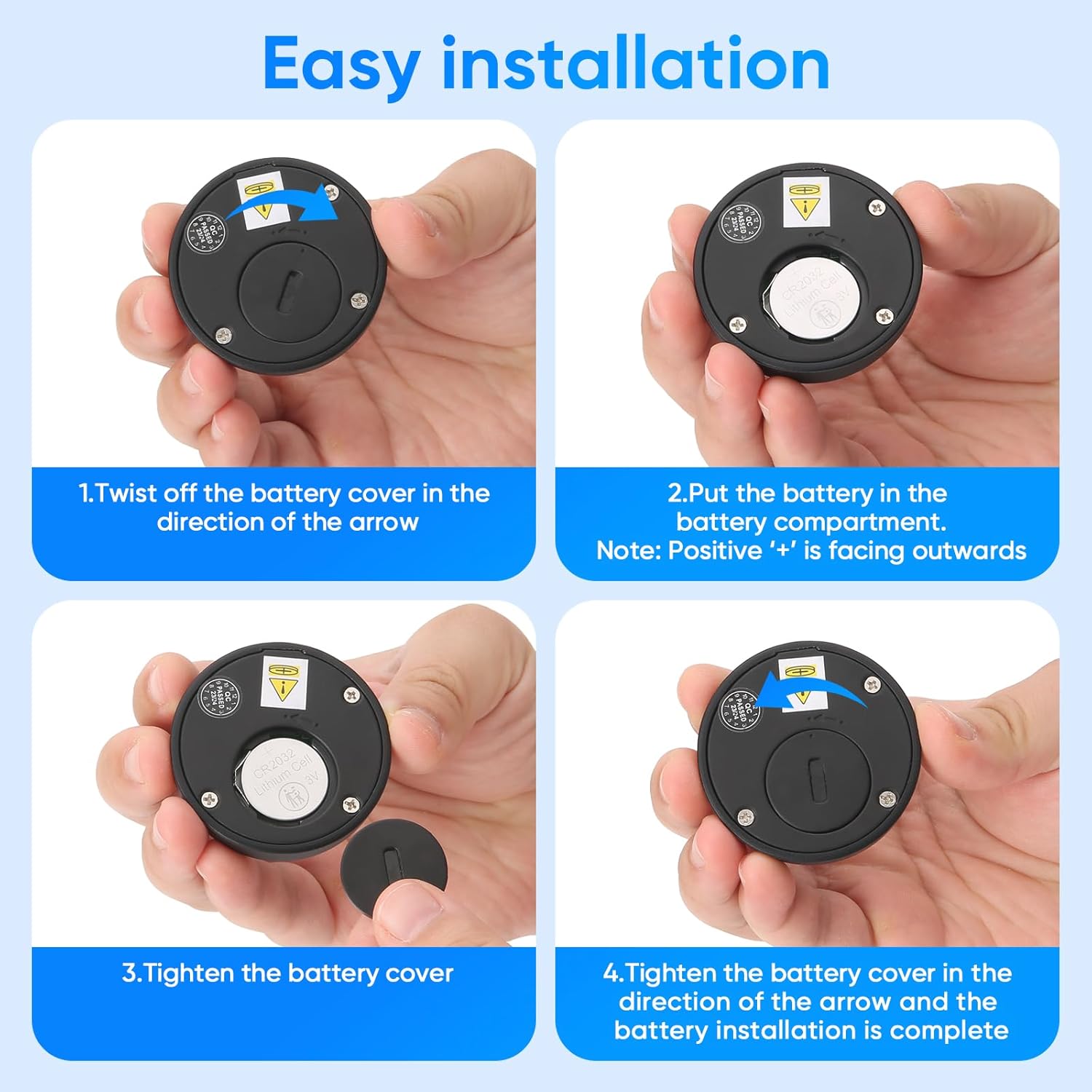
Image: All components included in the package, showing the lock body, striking plate, fingerprint remote panel, USB-C emergency key, screws, and installation panel.
- Lock Body
- Striking Plate
- Fingerprint Remote Panel
- USB-C Emergency Key
- Screws
- User Manual & Installation Panel
3. Specifications
| Feature | Detail |
|---|---|
| Brand | MYPIN |
| Model Name | HS0433 |
| Lock Type | Combination Lock |
| Material | Alloy Steel |
| Color | Black |
| Item Dimensions (L x W x H) | 1.9 x 1.9 x 1.9 inches |
| Item Weight | 6 ounces (0.17 Kilograms) |
| Unlocking Methods | Fingerprint, Remote Control, USB Key |
| Fingerprint Capacity | Up to 20 fingerprints |
| Remote Unlocking Range | Within 10 meters |
| Battery Type | 1 Lithium Ion battery (included) for remote, 3 AAA batteries (not included) for lock body |
| Emergency Power | USB-C Emergency Charge |
| Installation Type | Hole-less installation |
4. Safety Information
- Ensure the lock is installed securely to prevent accidental detachment.
- Keep the fingerprint sensor clean and dry for optimal performance.
- Do not expose the lock to extreme temperatures or moisture.
- Use only recommended battery types (3 AAA for lock body, 1 Lithium Ion for remote).
- In case of emergency, use the USB-C key or external power supply as instructed.
- Keep out of reach of children to prevent unauthorized access or tampering.
5. Installation Guide
The MYPIN cabinet lock is designed for hole-less installation, preserving your furniture. Follow these steps carefully:
5.1. Prepare for Installation

Image: Comparison showing the MYPIN lock's no-hole installation inside a drawer versus other locks requiring drilling. It also notes that double-paneled or double-layered drawer tops are not suitable for this installation method.
- Ensure the installation surface is clean and dry.
- Verify that your drawer or cabinet is not double-paneled or double-layered, as this may affect installation.
5.2. Install Lock Body and Striking Plate

Image: Six-step visual guide for installing the lock body and striking plate. Steps include marking position, tearing off sticker and pasting lock body, tightening screws, placing batteries, tearing off sticker and fixing lock catch, and completing installation.
- Mark Position: Use the provided location sticker and a pencil to mark the precise position for the lock body and striking plate on your drawer or cabinet. Ensure proper alignment for smooth operation.
- Attach Lock Body: Tear off the adhesive backing from the lock body. Carefully align it with your markings and firmly press it onto the inside of the drawer panel.
- Secure Lock Body: Use the provided screws and an electric drill (or screwdriver) to further secure the lock body in place. This prevents the lock from detaching.
- Insert Batteries: Open the battery compartment on the lock body and insert 3 AAA batteries (not included), ensuring correct polarity. Close the compartment.
- Attach Striking Plate: Tear off the adhesive backing from the striking plate. Align it with the lock body's latch mechanism on the cabinet frame and firmly press it into place.
- Secure Striking Plate: Use screws to permanently fix the striking plate. Test the drawer/cabinet closure to ensure the latch engages correctly.
5.3. Install Remote Panel Battery

Image: Four-step visual guide for installing the battery in the remote panel. Steps include twisting off the battery cover, placing the CR2032 button cell battery with the positive side outwards, tightening the battery cover, and completing the installation.
- Twist off the battery cover of the remote panel in the direction of the arrow.
- Place the CR2032 button cell battery into the battery compartment, ensuring the positive '+' side is facing outwards.
- Tighten the battery cover in the direction of the arrow.
- The battery installation is complete.
5.4. Installation Video
Video: A detailed guide on how to install the MYPIN Fingerprint Remote Control Cabinet Lock, demonstrating each step of the physical installation process.
6. Operating Instructions
This section details how to set up and use your MYPIN Fingerprint Remote Control Cabinet Lock.
6.1. Quick Guide for Fingerprint and Remote Operations

Image: A visual quick guide illustrating how to bind the lock body, add new fingerprints, unbind the lock body, add next fingerprints, and delete fingerprints using the remote panel.
6.2. Pairing the Remote Panel (Binding)
- Press the setting button on the lock body (located inside the battery compartment).
- Within 10 seconds, press your finger on the remote panel's sensor.
- The green light on the remote panel will blink twice, indicating successful pairing.
6.3. Unbinding the Remote Panel
- Place your registered finger on the remote panel's sensor and hold for 15 seconds until the yellow light flashes.
- Release your finger. All registered fingerprints will be deleted, and the remote control will be unbound from the lock body.
6.4. Registering Fingerprints
The lock supports up to 20 fingerprints.
- First Fingerprint (Administrator): Press and hold the remote panel's sensor until the green light appears. Release your finger. The blue light will appear. Press your finger on the sensor 6 times, lifting it slightly between each press. The green light will stop for 1 second to indicate successful registration.
- Additional Fingerprints: After the first fingerprint is registered, the blue light will remain on. To add more fingerprints, press another finger on the sensor 6 times. The green light will stop for 1 second to indicate successful registration. Repeat for up to 20 fingerprints.
- If you do not wish to add more fingerprints, wait for the blue light to go out.
6.5. Deleting Fingerprints
To delete all registered fingerprints:
- Place a registered finger on the remote panel's sensor and hold for 15 seconds until the yellow light flashes.
- Release your finger. All registered fingerprints will be deleted.
6.6. Remote Unlocking

Image: Demonstrates remote unlocking of a cabinet from a distance and direct fingerprint unlocking when the panel is fixed to the cabinet. The remote panel can be installed separately within 10 meters of the lock body.
Simply place your registered finger on the remote panel's sensor. The lock will unlock within 0.5 seconds. The remote panel can be used wirelessly within 10 meters of the lock body, or it can be fixed directly to the cabinet for direct access.
6.7. Automatic Locking
The lock features an auto-lock function. After unlocking, the latch will automatically extend after a period of time to ensure the cabinet is secured, even if you forget to close it manually.
6.8. Operating Instructions Video
Video: A comprehensive guide demonstrating how to operate and set up fingerprints on the MYPIN Fingerprint Remote Control Cabinet Lock, including pairing, unbinding, and registering new fingerprints.
7. Maintenance
7.1. Low Battery Alarm

Image: Illustrates the lock body, striking plate, and external socket, detailing the low voltage alarm thresholds: 3.8V (5 alarms, still locks), 3.7V (5 alarms, latch won't auto-lock), and 3.6V (5 alarms every 5 seconds, latch pops open automatically).
- Low Voltage Alarm (Below 3.8V): The lock will emit 5 alarms when unlocked, but will still function normally. Replace batteries soon.
- Ultra-Low Voltage Alarm (Below 3.7V): The lock will emit 5 alarms when unlocked, and the latch will no longer automatically lock. Replace batteries immediately.
- Very Low Voltage Alarm (Below 3.6V): The lock will detect low voltage every 5 seconds (5 alarms in a row), and the latch will pop open automatically. Replace batteries immediately.
7.2. Battery Replacement

Image: Shows the lock body with the battery compartment open, indicating the placement of 3 AAA batteries for ultra-low power consumption.
When the low battery alarm sounds, replace the 3 AAA batteries in the lock body. For the remote panel, replace the CR2032 button cell battery as described in the installation section. Ensure correct polarity during replacement.
7.3. Emergency Unlocking (USB-C Key)

Image: Shows the lock body with an external Type-C emergency power socket, allowing connection to a mobile power bank for unlocking when the internal batteries are depleted.
In case the batteries are completely depleted and the lock does not respond, you can use the provided USB-C emergency key or connect a power bank/mobile charger to the external Type-C socket on the lock body to supply temporary power and unlock it.
8. Troubleshooting
- Lock not responding: Check battery levels in both the lock body and the remote panel. Replace if necessary. Use the emergency USB-C key if batteries are completely dead.
- Fingerprint not recognized: Ensure your finger is clean and dry. Try different angles or re-register your fingerprint if issues persist.
- Remote panel not unlocking: Ensure the remote panel is within 10 meters of the lock body. Check battery levels. Re-pair the remote panel if necessary.
- Lock does not auto-lock: This may indicate ultra-low battery voltage (below 3.7V). Replace the lock body batteries immediately.
- Factory Restore: If you encounter persistent issues or wish to reset all settings, perform a factory restore. This will delete all registered fingerprints and unbind the remote. To perform a factory restore, connect the USB-C emergency key to the remote panel. Press and hold the fingerprint sensor until the red light flashes, then release. The lock will be restored to factory settings.
9. Warranty and Support
For warranty information, technical support, or any questions not covered in this manual, please refer to the product packaging or contact MYPIN customer service directly. Keep your purchase receipt for warranty claims.


