
Mastech MS2101
Mastech MS2101 AC/DC Digital Clamp Meter User Manual
Model: MS2101 | Brand: Mastech
1. Important Safety Information
Please read and understand all safety information and operating instructions before using this instrument. Improper use may result in electric shock or damage to the meter. Always adhere to local and national safety codes.
- Do not exceed the maximum input values specified for each function.
- Ensure the test leads are properly connected and in good condition before making any measurements.
- Do not use the meter if it appears damaged or if the insulation on the test leads is compromised.
- Exercise extreme caution when working with voltages above 30V AC RMS, 42V peak, or 60V DC. These voltages pose a shock hazard.
- Always disconnect the circuit power and discharge all high-voltage capacitors before measuring resistance, continuity, diodes, or capacitance.
- Replace batteries immediately when the low battery indicator appears to ensure accurate readings.
- This device is rated for CAT III 600V and CAT II 1000V. Adhere to these safety categories.
2. Product Overview
The Mastech MS2101 is a versatile AC/DC digital clamp meter designed for accurate measurement of current, voltage, resistance, capacitance, frequency, and temperature. It features auto-ranging capabilities and a clear digital display, making it suitable for both domestic and industrial electrical testing.
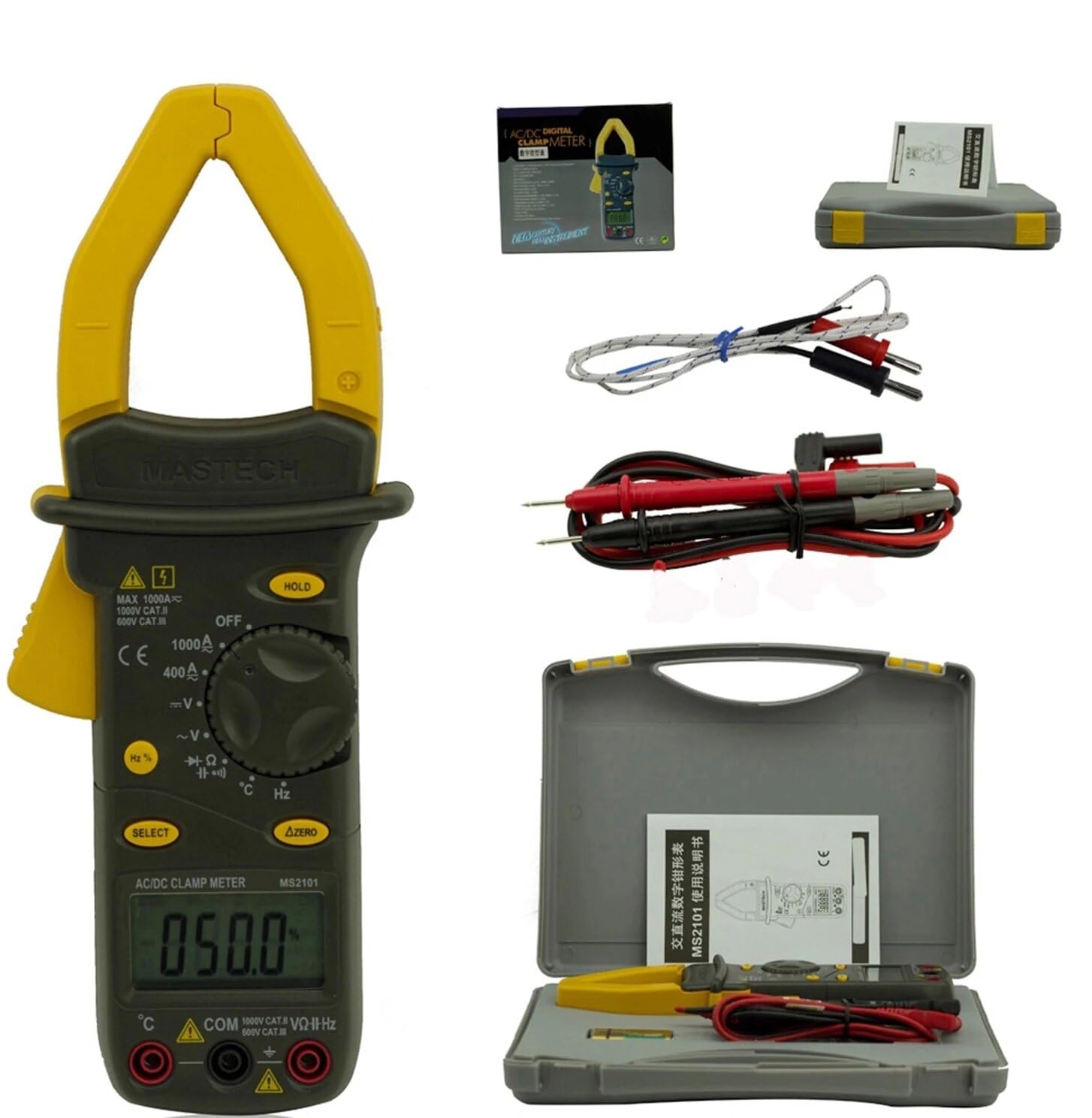
Image: Mastech MS2101 clamp meter with included test leads, temperature probe, and carrying case.
2.1 Key Features
- Display: 4000 counts
- Jaw Opening: Φ42mm / 1.7 inches
- Auto and Manual Ranging
- Auto Power Off function
- Diode Open Voltage: 2.2V
- Continuity Buzzer: Activates at <50±20Ω
- Data Hold function
- Low Battery Display indicator
3. Package Contents
Upon opening the package, verify that all items listed below are present and in good condition.

Image: Contents of the Mastech MS2101 package, including the meter, test leads, and documentation.
- Mastech MS2101 AC/DC Digital Clamp Meter
- Test Leads (one pair)
- K-Type Thermocouple (for temperature measurement)
- Carrying Bag
- Calibration Certificate
- Quick Start Guide
- Batteries (2 x LR44, included)
4. Device Layout and Controls
Familiarize yourself with the various parts and controls of your MS2101 clamp meter.

Image: Front view of the Mastech MS2101, highlighting the display, rotary switch, and function buttons.
- Current Clamp Jaw: Used for non-contact AC/DC current measurement.
- Jaw Trigger: Squeeze to open the current clamp jaw.
- Rotary Switch: Selects the desired measurement function (OFF, V, A, Ω, Capacitance, Hz, Diode, Continuity, Temperature).
- LCD Display: Shows measurement readings, units, and function indicators.
- HOLD Button: Freezes the current reading on the display.
- SELECT Button: Toggles between AC/DC modes or different functions within a rotary switch position (e.g., Diode/Continuity, AC/DC Voltage).
- ΔZERO Button: Used to zero out DC current readings or relative measurements.
- COM Input Jack: Common (negative) input for test leads.
- VΩHz Input Jack: Positive input for voltage, resistance, frequency, capacitance, diode, and continuity measurements.
- Temperature Input Jack: Specific input for the K-type thermocouple.
5. Initial Setup
5.1 Battery Installation
The Mastech MS2101 requires two LR44 batteries for operation. These are typically included in the package.

Image: Back view of the Mastech MS2101, indicating the location of the battery compartment screws.
- Ensure the meter is turned OFF.
- Locate the battery compartment on the back of the meter.
- Use a screwdriver to remove the screws securing the battery cover.
- Carefully remove the battery cover.
- Insert two LR44 batteries, observing the correct polarity (+ and -) as indicated inside the compartment.
- Replace the battery cover and secure it with the screws.
6. Operating Instructions
6.1 Power On/Off
To power on the meter, rotate the rotary switch from the 'OFF' position to any desired measurement function. To power off, rotate the switch back to 'OFF'.
6.2 Function Selection
Turn the rotary switch to the desired measurement function. For functions with multiple modes (e.g., AC/DC Voltage, Diode/Continuity), press the 'SELECT' button to toggle between them.
6.3 Measuring AC/DC Current
- Rotate the switch to the 'A' (Current) position.
- Press 'SELECT' to choose between AC or DC current measurement.
- Press the jaw trigger to open the clamp jaw.
- Enclose only one conductor of the circuit within the clamp jaw. Ensure the jaw is fully closed.
- Read the current value on the LCD display.
- For DC current, use the 'ΔZERO' button to zero the display before measurement if necessary.
6.4 Measuring AC/DC Voltage
- Rotate the switch to the 'V' (Voltage) position.
- Press 'SELECT' to choose between AC or DC voltage measurement.
- Insert the red test lead into the 'VΩHz' jack and the black test lead into the 'COM' jack.
- Connect the test probes in parallel to the circuit or component you wish to measure.
- Read the voltage value on the LCD display.
6.5 Measuring Resistance
- Rotate the switch to the 'Ω' (Resistance) position.
- Insert the red test lead into the 'VΩHz' jack and the black test lead into the 'COM' jack.
- Ensure the circuit or component is de-energized before connecting the test probes across it.
- Read the resistance value on the LCD display.
6.6 Measuring Capacitance
- Rotate the switch to the 'Capacitance' position.
- Insert the red test lead into the 'VΩHz' jack and the black test lead into the 'COM' jack.
- Ensure the capacitor is fully discharged before connecting the test probes across it.
- Read the capacitance value on the LCD display.
6.7 Measuring Frequency/Duty Cycle
- Rotate the switch to the 'Hz' (Frequency) position.
- Insert the red test lead into the 'VΩHz' jack and the black test lead into the 'COM' jack.
- Connect the test probes across the signal source.
- Read the frequency or duty cycle value on the LCD display. Press 'SELECT' to toggle between frequency and duty cycle.
6.8 Diode Test
- Rotate the switch to the Diode/Continuity position. Press 'SELECT' until the diode symbol appears.
- Insert the red test lead into the 'VΩHz' jack and the black test lead into the 'COM' jack.
- Connect the red probe to the anode and the black probe to the cathode of the diode.
- Read the forward voltage drop on the display. Reverse the probes to check for open circuit (OL) in reverse bias.
6.9 Continuity Test
- Rotate the switch to the Diode/Continuity position. Press 'SELECT' until the continuity buzzer symbol appears.
- Insert the red test lead into the 'VΩHz' jack and the black test lead into the 'COM' jack.
- Connect the test probes across the circuit or component.
- If the resistance is below approximately 50Ω, the buzzer will sound, indicating continuity.
6.10 Temperature Measurement
- Rotate the switch to the '°C/°F' (Temperature) position.
- Insert the K-type thermocouple into the dedicated temperature input jacks, observing polarity.
- Place the thermocouple tip on or near the object whose temperature you wish to measure.
- Read the temperature on the LCD display. Press 'SELECT' to toggle between Celsius and Fahrenheit.
6.11 Data Hold Function
Press the 'HOLD' button to freeze the current reading on the display. Press it again to release the hold and resume live measurements.
6.12 Zeroing (ΔZERO) Function
In DC current mode, press the 'ΔZERO' button to zero the display before making a measurement. This compensates for any residual magnetic fields or offsets, ensuring more accurate DC current readings.
6.13 Auto Power Off
The meter will automatically power off after approximately 15 minutes of inactivity to conserve battery life. To reactivate, turn the rotary switch to 'OFF' and then back to the desired function.
7. Maintenance
7.1 Cleaning
Wipe the meter's casing with a damp cloth and a mild detergent. Do not use abrasives or solvents. Ensure the meter is completely dry before use.
7.2 Battery Replacement
When the low battery indicator appears on the display, replace the batteries as described in Section 5.1. Always use two new LR44 batteries.
7.3 Storage
If the meter is not used for an extended period, remove the batteries to prevent leakage and damage. Store the meter in a cool, dry place, away from direct sunlight and extreme temperatures.
8. Troubleshooting
- Meter does not power on: Check battery installation and ensure batteries are not depleted.
- No reading or 'OL' displayed: Ensure test leads are properly connected and making good contact. For current measurements, ensure only one conductor is within the clamp jaw. For resistance/continuity, ensure the circuit is de-energized. 'OL' (Overload) indicates the measured value is beyond the meter's range.
- Inaccurate readings: Check battery level. Ensure the correct function is selected. For DC current, use the 'ΔZERO' function.
- Buzzer not sounding in continuity mode: The resistance may be too high (above 50Ω), or the circuit is open.
9. Technical Specifications
Detailed specifications for the Mastech MS2101 clamp meter are provided below.

Image: Table detailing the measurement ranges, resolutions, and accuracies of the Mastech MS2101.
| Measurement | Range | Resolution | Accuracy |
|---|---|---|---|
| DC Voltage | 400mV/4V/40V/400V 1000V | 0.1mV/1mV/10mV/0.1V 1V | ±(0.7%+1) ±(0.8%+3) |
| AC Voltage | 4V/40V/400V 750V | 1mV/10mV/0.1V 1V | ±(0.8%+5) ±(1.0%+10) |
| DC Current | 400A/1000A | 0.1A/1A | ±(3.0%+3) |
| AC Current | 400A/1000A | 0.1A/1A | ±(3.0%+3) |
| Resistance | 400Ω/4kΩ/40kΩ/400kΩ/4MΩ 40MΩ | 0.1Ω/1Ω/10Ω/100Ω/1kΩ 10kΩ | ±(1.2%+1) ±(2.0%+3) |
| Capacitance | 4nF/40nF/400nF 4µF/40µF/100µF | 1pF/10pF/0.1nF 1nF/10nF/100nF | ±(4.0%+10) ±(4.0%+10) |
| Frequency | 40Hz/400Hz/4kHz/40kHz/100kHz | 0.01Hz/0.1Hz/1Hz/10Hz/0.1kHz | ±(2.0%+1) |
| Duty Cycle | 0.1% ~ 99.9% | 0.10% | ±(2.0%+2) |
| Temperature | -40°C ~ 0°C 1°C ~ 400°C 401°C ~ 750°C | 1°C 1°C 1°C | ±(1.0%+6) ±(1.0%+3) ±(1.0%+5) |
| Display | 4000 counts | ||
| Jaw Opening | 42mm / 1.7 inches | ||
| Continuity Buzzer | <50±20Ω | ||
| Diode Open Voltage | 2.2V | ||
| Power Source | 2 x LR44 batteries | ||
| Dimensions (L x W x H) | 7.87 x 5.91 x 9.84 inches | ||
| Weight | 1 Kilogram (2.2 Pounds) | ||
10. Warranty and Support
The Mastech MS2101 Digital Clamp Meter comes with a 1-year warranty from the date of purchase, covering manufacturing defects. Please retain your proof of purchase for warranty claims.
For technical support, product information, or warranty inquiries, please visit the official Mastech website or contact their customer service:
- Official Mastech Website: www.mastech-group.com
- Support Page: http://www.mastech-group.com/support.php?n=0
Related documentsMS2101


Ask a question about this manual
Ask about setup, troubleshooting, compatibility, parts, safety, or missing instructions. Manuals+ will review the question and use this page’s manual context to help answer it.