
1. Introduction
This instruction manual provides essential information for the safe and effective operation of your Mastech MS2000G Digital Clamp Meter. Please read this manual thoroughly before use and retain it for future reference. This device is designed for measuring AC current, AC/DC voltage, resistance, continuity, diode, frequency, and temperature in various electrical applications.
2. Safety Information
WARNING: To avoid electric shock or personal injury, always follow these safety precautions.
- Always disconnect measuring leads before removing the battery cover.
- Do not apply voltage or current that exceeds the maximum specified limits for the meter.
- Ensure the rotary switch is in the correct position for the desired measurement before connecting to the circuit.
- Inspect test leads for damaged insulation or exposed metal before each use. Replace if damaged.
- Do not use the meter if it appears damaged or if the case is open.
- The Mastech MS2000G is rated for CAT II 1000V and CAT III 600V. Adhere to these category ratings for safe operation.
- Exercise extreme caution when working with live circuits.
For detailed safety guidelines, refer to relevant electrical safety standards.
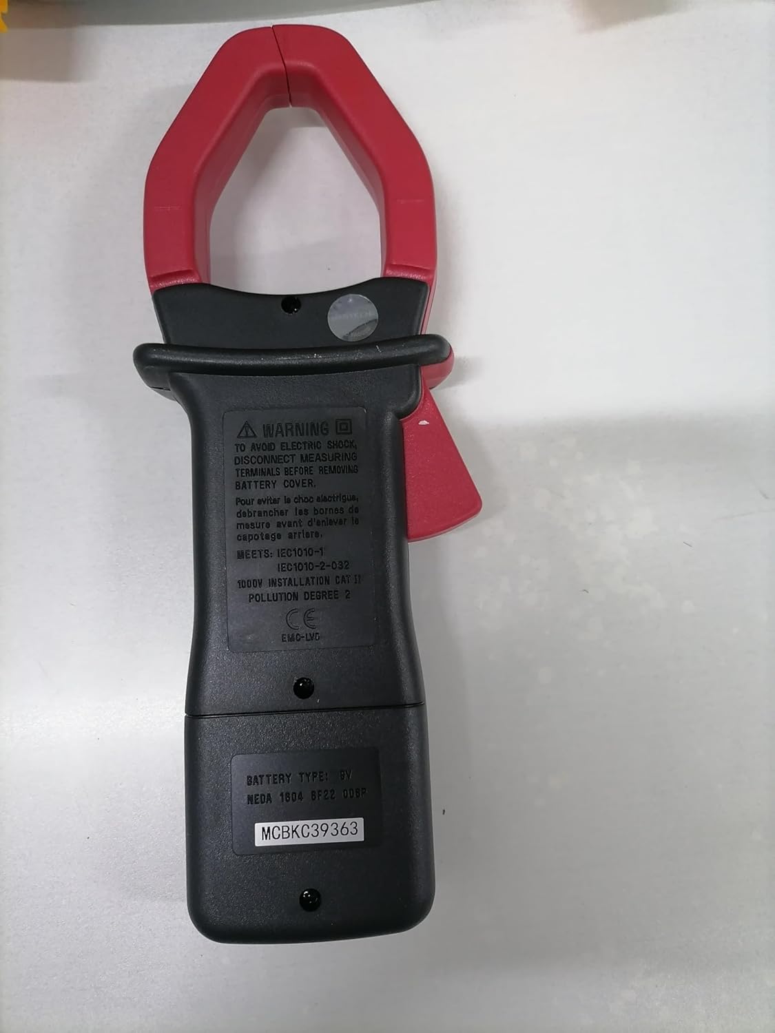
Rear view of the Mastech MS2000G Digital Clamp Meter, showing the battery compartment and safety warnings, including instructions to disconnect leads before opening.
3. Product Features
- 2000 Counts Digital Display
- Jaw Opening: 55mm (2.2 inches)
- Diode Open Voltage: 3.0V
- Continuity Buzzer: Activates below 30Ω
- Data Hold Function
- Display Backlight for low-light conditions
- Low Battery Display Indicator
4. Product Overview
The Mastech MS2000G features a robust design for professional and home use. Key components include:
- Clamp Jaw: Used for non-contact AC current measurement.
- Rotary Switch: Selects measurement functions (AC Current, Voltage, Resistance, etc.).
- LCD Display: Shows measurement readings, units, and indicators.
- Input Jacks: For connecting test leads for voltage, resistance, continuity, diode, frequency, and temperature measurements.
- Data Hold Button: Freezes the current reading on the display.
- Backlight Button: Illuminates the display for better visibility.

Front view of the Mastech MS2000G Digital Clamp Meter, highlighting the display, rotary switch, and clamp jaw.
5. Setup
5.1 Battery Installation
- Ensure the meter is turned OFF and all test leads are disconnected.
- Locate the battery compartment cover on the rear of the meter.
- Use a screwdriver to loosen the screw(s) securing the battery cover.
- Remove the cover.
- Insert a new 9V battery, observing the correct polarity (+ and -).
- Replace the battery cover and secure it with the screw(s).
5.2 Connecting Test Leads
For measurements requiring test leads (voltage, resistance, continuity, diode, frequency, temperature):
- Insert the red test lead into the VHzΩ input jack.
- Insert the black test lead into the COM input jack.
- For temperature measurements, connect the K-type thermocouple to the designated input terminals, observing polarity.
6. Operating Instructions
To operate the Mastech MS2000G, turn the rotary switch to the desired function. The display will show the measurement reading.
6.1 AC Current Measurement
- Turn the rotary switch to the 'A' (AC Current) range.
- Open the clamp jaw by pressing the trigger.
- Encircle only one conductor of the circuit with the clamp jaw. Ensure the jaw is fully closed.
- Read the AC current value on the display.
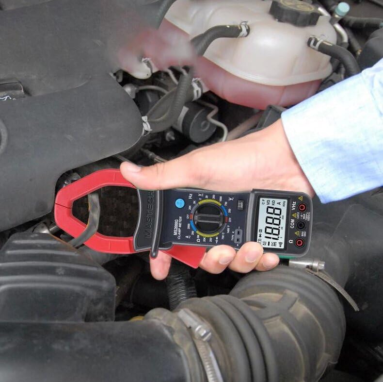
Demonstration of the Mastech MS2000G measuring AC current around a single conductor.
6.2 AC/DC Voltage Measurement
- Connect the test leads as described in Section 5.2.
- Turn the rotary switch to the 'V~' (AC Voltage) or 'V=' (DC Voltage) range.
- Connect the test probes in parallel to the circuit or component under test.
- Read the voltage value on the display.
6.3 Resistance Measurement
- Connect the test leads.
- Turn the rotary switch to the 'Ω' (Resistance) range.
- Ensure the circuit or component is de-energized before connecting the probes.
- Connect the test probes across the component.
- Read the resistance value on the display.
6.4 Continuity Test
- Connect the test leads.
- Turn the rotary switch to the 'Ω' (Resistance) range and press the 'SELECT' button if necessary to choose continuity mode (indicated by a buzzer symbol).
- Connect the test probes across the circuit or component.
- If the resistance is below approximately 30Ω, the buzzer will sound, indicating continuity.
6.5 Diode Test
- Connect the test leads.
- Turn the rotary switch to the 'Ω' (Resistance) range and press 'SELECT' to choose diode mode (indicated by a diode symbol).
- Connect the red probe to the anode and the black probe to the cathode of the diode.
- The display will show the forward voltage drop. Reverse the probes; the display should show 'OL' (Open Loop) for a good diode.
6.6 Frequency Measurement
- Connect the test leads.
- Turn the rotary switch to the 'Hz' (Frequency) range.
- Connect the test probes to the circuit where frequency is to be measured.
- Read the frequency value on the display.
6.7 Temperature Measurement
- Connect the K-type thermocouple to the designated input terminals, observing polarity.
- Turn the rotary switch to the '°C' or '°F' (Temperature) range.
- Place the thermocouple probe on or near the object whose temperature is to be measured.
- Read the temperature value on the display.
6.8 Data Hold Function
Press the 'HOLD' button to freeze the current reading on the display. Press it again to release and resume live measurements.
6.9 Display Backlight
Press the 'LIGHT' button to turn on the display backlight for improved visibility in dimly lit environments. Press it again to turn off the backlight.
7. Maintenance
7.1 Cleaning
Wipe the meter's case with a damp cloth and mild detergent. Do not use abrasives or solvents. Ensure the meter is dry before use.
7.2 Battery Replacement
When the 'Low Battery' indicator appears on the display, replace the 9V battery as described in Section 5.1. Prompt battery replacement ensures accurate readings.
7.3 Storage
If the meter is not used for an extended period, remove the battery to prevent leakage and damage. Store the meter in a cool, dry place, away from direct sunlight and extreme temperatures.
8. Troubleshooting
- No Display/Faint Display: Check battery installation and replace the 9V battery if necessary.
- Incorrect Readings: Ensure the rotary switch is set to the correct function and range. Verify test lead connections. Check for damaged test leads.
- 'OL' on Display: Indicates an over-range condition or an open circuit. Select a higher range or check the circuit connection.
- Buzzer Not Sounding in Continuity Mode: The resistance may be above the continuity threshold (30Ω), or the circuit is open.
9. Specifications
| Parameter | Specification |
|---|---|
| Display | 2000 Counts |
| Jaw Opening | 55mm (2.2") |
| AC Voltage | 750V |
| DC Voltage | 1000V |
| AC Current | 1000A |
| Resistance | 2MΩ |
| Frequency | 20kHz |
| Continuity | <30Ω (Buzzer) |
| Diode Open Voltage | 3.0V |
| Temperature (Type K) | -0°C to 750°C (32°F to 1382°F) |
| Safety Rating | CAT II 1000V, CAT III 600V |
| Power Source | 9V Battery (included) |
| Product Dimensions | 7.87 x 5.91 x 9.84 inches |
| Item Weight | 1 Kilogram (2.2 Pounds) |

Detailed specifications and features for the Mastech MS2000G and other models.
10. What's in the Box
The Mastech MS2000G package typically includes:
- Mastech MS2000G Digital Clamp Meter
- Test Leads (one pair)
- Wrapping Case
- K-Type Thermocouple
- 9V Battery
- Calibration Certificate
- Quick Start Guide / User Manual

Contents of the Mastech MS2000G package, including the clamp meter and accessories.
11. Warranty and Support
For warranty information and technical support, please refer to the documentation included with your product or contact the seller/manufacturer directly. Keep your purchase receipt as proof of purchase.


