1. Introduction
The Mastech MS8250D is a high-performance digital multimeter designed for accurate measurement of AC/DC voltage, AC/DC current, resistance, capacitance, frequency, and temperature. It features a 6600-count display, auto/manual ranging, True RMS, Non-Contact Voltage (NCV) detection, diode and continuity testing, and a USB interface for PC connectivity. This manual provides detailed instructions for safe and effective use of the device.
Key Features:
- 6600-count digital display
- Automatic and Manual Ranging
- True RMS measurement
- Non-Contact Voltage (NCV) detection
- Diode and Continuity Tester (buzzer < 50Ω)
- MAX/MIN value recording
- Data Hold function
- Display Backlight
- Auto Power Off
- Relative Measurement mode
- Low Battery Indication
- USB Interface for Windows OS
2. Safety Information
WARNING: To avoid electric shock or personal injury, and to avoid damage to the meter or to the equipment under test, read all safety information carefully before using the meter. This device complies with CE, RoHS, and UL safety standards.
- Always ensure the test leads are in good condition and properly connected.
- Do not apply more than the rated voltage, as marked on the meter, between the terminals or between any terminal and earth ground.
- Use caution when working with voltages above 30V AC RMS, 42V peak, or 60V DC. These voltages pose a shock hazard.
- Before measuring current, ensure the circuit is de-energized and the meter is connected in series.
- Always disconnect the test leads from the circuit before changing functions or ranges.
- Do not use the meter if it appears damaged or if the case is open.
- Replace the battery as soon as the low battery indicator appears to ensure accurate readings.
- Adhere to the specified measurement categories (CAT III 1000V / CAT IV 600V) for safe operation.
3. Product Overview
Familiarize yourself with the components of your Mastech MS8250D Digital Multimeter.

Image 3.1: Front view of the Mastech MS8250D Digital Multimeter, showing the display, function dial, and input jacks. The display shows "1.987 V", indicating a voltage measurement. The function dial is set to T-RMS. Input jacks are labeled for µA mA, A, VΩHz%, and COM.
Main Components:
- LCD Display: Shows measurement readings, units, and function indicators.
- Function Dial: Used to select the desired measurement function (e.g., Voltage, Current, Resistance, Diode, Continuity, Temperature).
- Function Buttons:
- HOLD: Freezes the current display reading.
- RANGE: Switches between auto and manual ranging.
- REL: Activates relative measurement mode.
- MAX/MIN: Records maximum and minimum values.
- FUNC: Selects sub-functions within a dial position (e.g., AC/DC, Diode/Continuity).
- T-RMS: (Indicated on dial) True RMS measurement.
- NCV: Non-Contact Voltage detection.
- Backlight Button: Activates display backlight.
- Input Jacks:
- COM: Common terminal for all measurements (negative lead).
- VΩHz%: Input for voltage, resistance, frequency, capacitance, and diode/continuity measurements (positive lead).
- µA mA: Input for microampere and milliampere current measurements (positive lead). Fused for protection.
- A: Input for ampere current measurements (positive lead). Fused for protection.
Included Components:
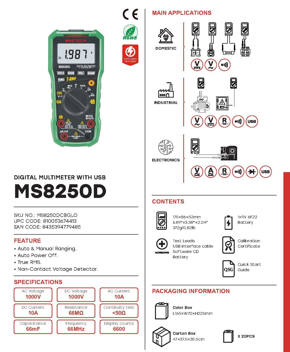
Image 3.2: Diagram showing the Mastech MS8250D Multimeter and its included accessories. The image also illustrates typical applications in domestic, industrial, and electronics settings.
- Mastech MS8250D Digital Multimeter
- Test Leads (Red and Black)
- 1x 9V 6F22 Battery (pre-installed or included separately)
- USB Interface Cable
- Software CD (for Windows OS)
- Calibration Certificate
- Quick-Start Guide
4. Setup
4.1 Battery Installation
The MS8250D requires one 9V 6F22 battery for operation. Two LR44 batteries are also mentioned in specifications, likely for a different internal component or an error in data. For the main power, use the 9V battery.
- Ensure the multimeter is turned OFF.
- Locate the battery compartment cover on the back of the meter.
- Use a screwdriver to loosen the screw(s) securing the cover.
- Remove the cover.
- Connect the 9V battery to the battery clips, observing correct polarity (+ and -).
- Place the battery into the compartment.
- Replace the battery compartment cover and secure it with the screw(s).
Note: The meter also uses 2 LR44 batteries, which are typically included and pre-installed for specific functions like the backlight or non-contact voltage detection. Refer to the quick-start guide for specific details on these smaller batteries if replacement is needed.
4.2 Connecting Test Leads
Always connect the black test lead to the COM jack. Connect the red test lead to the appropriate input jack based on the measurement type:
- For Voltage, Resistance, Capacitance, Frequency, Diode, and Continuity measurements: Connect the red lead to the VΩHz% jack.
- For Current measurements (µA or mA): Connect the red lead to the µA mA jack.
- For High Current measurements (A): Connect the red lead to the A jack.
Ensure the test leads are fully inserted into the jacks.
5. Operating Instructions
5.1 Power On/Off
To turn the meter ON, rotate the function dial from the "OFF" position to any desired measurement function. To turn the meter OFF, rotate the function dial back to the "OFF" position.
The meter features an Auto Power Off function to conserve battery life. It will automatically power off after a period of inactivity. To disable or re-enable this feature, refer to the quick-start guide or the full user manual provided on the software CD.
5.2 Auto Ranging and Manual Ranging
The MS8250D defaults to Auto Ranging, which automatically selects the best measurement range. Press the RANGE button to switch to Manual Ranging. In manual ranging, each press of the RANGE button cycles through available ranges. To return to auto ranging, press and hold the RANGE button.
5.3 Measuring AC/DC Voltage (V)
- Set the function dial to the V~ (AC Voltage) or V- (DC Voltage) position.
- Connect the black test lead to the COM jack and the red test lead to the VΩHz% jack.
- Connect the test probes across the circuit or component to be measured.
- Read the voltage value on the display. The meter will automatically detect AC or DC if the dial is set to the combined V position, or you can use the FUNC button to toggle between AC and DC if available on your model.
5.4 Measuring AC/DC Current (A, mA, µA)
WARNING: Never connect the meter in parallel to a voltage source when measuring current. This can blow the fuse or damage the meter.
- Turn OFF the power to the circuit.
- Set the function dial to the A~ (AC Current), A- (DC Current), mA~, mA-, µA~, or µA- position.
- Connect the black test lead to the COM jack.
- Connect the red test lead to the A jack for high current, or µA mA jack for low current.
- Open the circuit where the current is to be measured and connect the meter in series with the load.
- Apply power to the circuit.
- Read the current value on the display. Use the FUNC button to toggle between AC and DC if needed.
5.5 Measuring Resistance (Ω)
- Set the function dial to the Ω position.
- Connect the black test lead to the COM jack and the red test lead to the VΩHz% jack.
- Ensure the circuit or component under test is de-energized.
- Connect the test probes across the component.
- Read the resistance value on the display.
5.6 Diode Test and Continuity Test
- Set the function dial to the Diode/Continuity position (often shared with resistance or capacitance).
- Connect the black test lead to the COM jack and the red test lead to the VΩHz% jack.
- Use the FUNC button to select between Diode Test and Continuity Test.
- For Diode Test: Connect the red probe to the anode and the black probe to the cathode of the diode. The display will show the forward voltage drop (typically 0.5V to 0.8V for silicon diodes). Reversing the probes should show "OL" (Open Loop).
- For Continuity Test: Connect the probes across the circuit or component. If resistance is less than approximately 50Ω, the buzzer will sound, indicating continuity.
5.7 Measuring Capacitance (F)
- Set the function dial to the Capacitance position (often shared with resistance or diode).
- Connect the black test lead to the COM jack and the red test lead to the VΩHz% jack.
- Ensure the capacitor is fully discharged before testing to avoid damage to the meter.
- Connect the test probes across the capacitor terminals.
- Read the capacitance value on the display.
5.8 Measuring Frequency (Hz) and Duty Cycle (%)
- Set the function dial to the Hz% position (often shared with voltage).
- Connect the black test lead to the COM jack and the red test lead to the VΩHz% jack.
- Connect the test probes across the signal source.
- The display will show the frequency. Press the FUNC button to toggle to Duty Cycle measurement if available.
5.9 Non-Contact Voltage (NCV) Detection
- Set the function dial to the NCV position.
- Hold the meter with the NCV sensor (usually at the top of the meter) near a live AC voltage source.
- The meter will indicate the presence of AC voltage through an audible beep and/or visual indicator (e.g., LED).
5.10 USB Interface (Windows OS)
The MS8250D includes a USB interface for connecting to a computer running Windows OS. This allows for data logging and real-time monitoring of measurements. Install the provided software from the CD and follow the on-screen instructions for driver installation and software usage.
6. Maintenance
6.1 Cleaning
Wipe the meter's case with a damp cloth and a mild detergent. Do not use abrasives or solvents. Ensure the meter is completely dry before use.
6.2 Battery Replacement
When the low battery indicator appears on the display, replace the 9V battery immediately to ensure accurate readings. Follow the steps in Section 4.1 Battery Installation.
6.3 Fuse Replacement
If the meter fails to measure current, the fuse may be blown. Fuses are located inside the meter. To replace a fuse:
- Ensure the meter is turned OFF and all test leads are disconnected.
- Open the battery compartment cover (and potentially the main case, depending on design).
- Carefully remove the old fuse.
- Replace with a fuse of the exact same type and rating (e.g., F600mA/250V for mA/µA range, F10A/250V for A range). Refer to the meter's internal markings or the full manual for specific fuse ratings.
- Reassemble the meter, ensuring all screws are tightened.
WARNING: Never use a fuse with a different rating or bypass the fuse. This can damage the meter and pose a serious safety hazard.
7. Troubleshooting
| Problem | Possible Cause | Solution |
|---|---|---|
| Meter does not power on. | Dead battery. | Replace the 9V battery. |
| "OL" (Overload) displayed. | Measurement exceeds selected range or meter's maximum capacity. | Switch to a higher range (if in manual ranging) or ensure the measurement is within the meter's limits. |
| No current reading. | Blown fuse; incorrect lead connection; open circuit. | Check and replace fuse if necessary. Ensure leads are connected correctly (in series). Verify circuit continuity. |
| Inaccurate readings. | Low battery; poor lead contact; external interference. | Replace battery. Ensure leads are firmly connected. Move away from strong electromagnetic fields. |
| Display shows "USB" but no PC connection. | Drivers not installed; incorrect software settings. | Install drivers from the provided CD. Refer to software manual for connection instructions. |
8. Specifications
The following table details the technical specifications of the Mastech MS8250D Digital Multimeter.

Image 8.1: Detailed specifications table for the Mastech MS8250D, outlining ranges, resolutions, and accuracies for various measurement functions.
| Function | Range | Resolution | Accuracy |
|---|---|---|---|
| DC Voltage | |||
| 660mV | 0.1mV | ±(0.8%+3) | |
| 6.6V/66V/660V/1000V | 1mV/10mV/0.1V/1V | ±(0.5%+5) | |
| AC Voltage (True RMS) | |||
| 660mV | 0.1mV | ±(1.5%+5) | |
| 6.6V/66V | 1mV/10mV | ±(1.2%+5) | |
| 660V/1000V | 0.1V/1V | ±(1.0%+3) | |
| DC Current | |||
| 660µA/6600µA/66mA/660mA | 0.1µA/1µA/10µA/0.1mA | ±(1.0%+5) | |
| 10A | 10mA | ±(2.0%+5) | |
| AC Current (True RMS) | |||
| 660µA/6600µA/66mA/660mA | 0.1µA/1µA/0.01mA/0.1mA | ±(1.5%+5) | |
| 10A | 10mA | ±(3.0%+5) | |
| Resistance | |||
| 660Ω / 6.6kΩ / 66kΩ / 660kΩ / 6.6MΩ | 0.1Ω / 1Ω / 10Ω / 100Ω / 1kΩ | ±(0.8%+5) | |
| 66MΩ | 10kΩ | ±(1.5%+5) | |
| Capacitance | |||
| 6.6nF/66nF/660nF/6.6µF/66µF | 1pF/10pF/0.1nF/1nF/10nF | ±(4.0%+5) | |
| 600µF | 1µF | ±(3.0%+5) | |
| 6.6mF/66mF | 1µF/10µF | ±(4.0%+5) | |
| Frequency | |||
| 66Hz/660Hz/6.6kHz/66kHz | 0.01Hz/0.1Hz/1Hz/10Hz | ±(1.5%+5) | |
| 660kHz/6.6MHz/66MHz | 0.1kHz/1kHz/10kHz | ±(1.5%+5) | |
| Duty Cycle | |||
| 0.1%~99.9% | 0.1% | ±(2.0%+5) | |
General Specifications:
- Display: 6600 Counts
- Power Source: 1x 9V 6F22 Battery (main power), 2x LR44 batteries (auxiliary, e.g., backlight)
- Auto Power Off: Yes
- True RMS: Yes
- Non-Contact Voltage (NCV) Detector: Yes
- Diode Open Voltage: 3.2V
- Continuity Buzzer: < 50Ω
- MAX/MIN: Yes
- Data Hold: Yes
- Low Battery Display: Yes
- Display Backlight: Yes
- USB Interface: Yes (Windows OS)
- Safety Rating: CAT III 1000V / CAT IV 600V
- Measurement Accuracy: 0.4% (general, specific accuracies per function in table)
- Operating Voltage (Min): 3.2 Volts
- Upper Temperature Rating: 50 Degrees Celsius
- Dimensions (L x W x H): 20 x 15 x 25 cm
- Item Weight: 1 kg
- Material: Acrylonitrile Butadiene Styrene (ABS)
- Color: Blue
- Manufacturer: MASTECH
- Country of Origin: Taiwan
- Certifications: CE, RoHS, UL
9. Warranty and Support
Mastech products are designed for reliability and durability. For specific warranty information, please refer to the warranty card included with your product or contact Mastech customer support directly. Typically, Mastech offers a limited warranty against defects in materials and workmanship.
For technical support, troubleshooting assistance, or warranty claims, please contact your authorized Mastech dealer or visit the official Mastech website for contact information.
EU Spare Part Availability Duration: 1 Year


