Introduction
This manual provides essential information for the safe and effective installation, operation, and maintenance of your TOPINCN 3-Phase DIN Rail Voltmeter Ammeter Overvoltage Overcurrent Protector. This device is designed to monitor three-phase AC voltage and current, providing automatic protection against overvoltage, undervoltage, and overcurrent conditions to safeguard electrical equipment.
Safety Information
WARNING: Installation and maintenance should only be performed by qualified personnel. Disconnect all power before installation or servicing to prevent electric shock or equipment damage.
- Ensure the device is installed in a dry, well-ventilated area, away from direct sunlight and corrosive gases.
- Verify that the supply voltage and current ratings match the device specifications.
- Do not operate the device if it appears damaged.
- Proper grounding is essential for safe operation.
Product Overview
The TOPINCN CHLT 63 is a compact 3-phase protection device designed for DIN rail mounting. It features a digital display for real-time monitoring of voltage and current across three phases (L1, L2, L3) and provides automatic power cut-off in case of abnormal electrical conditions.
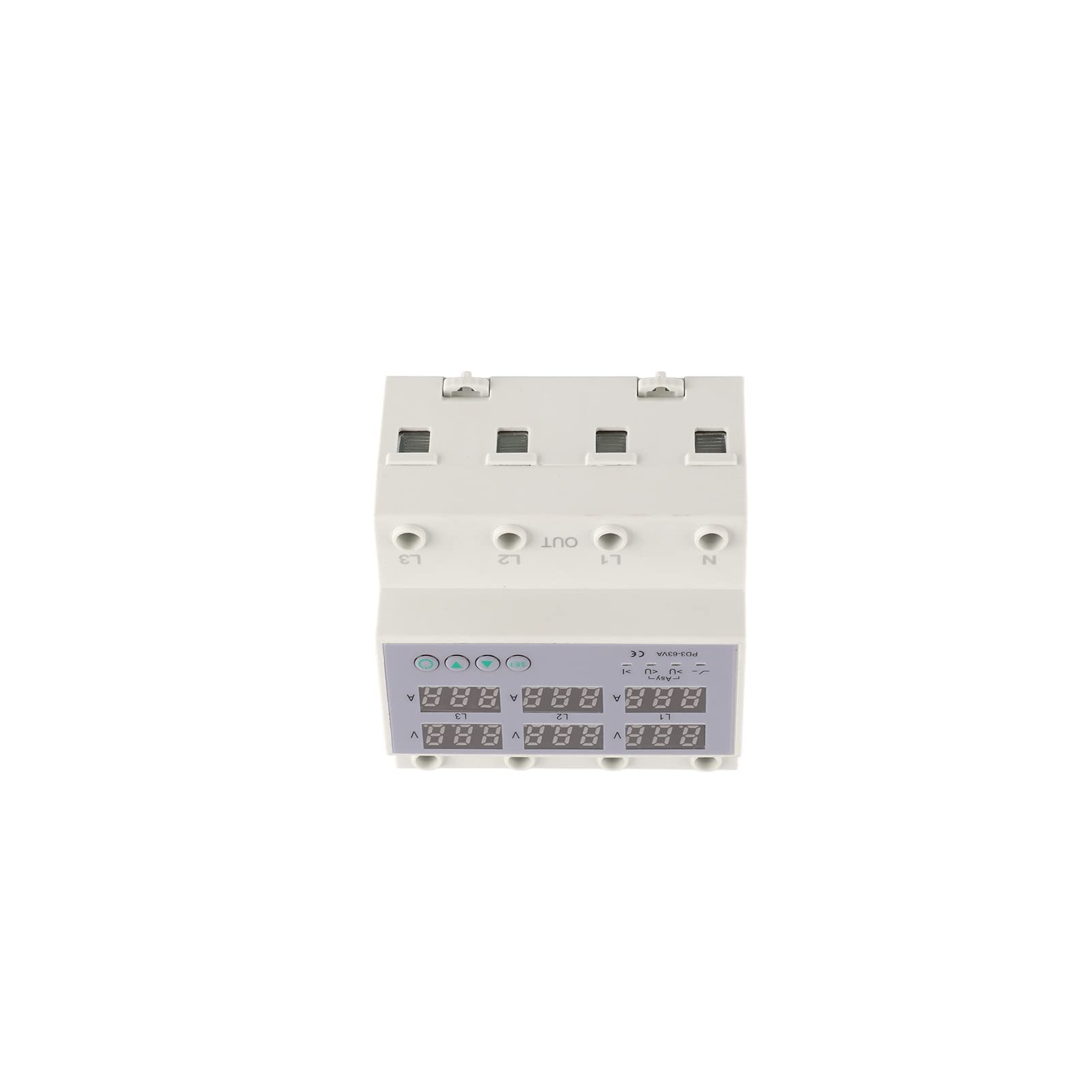
Figure 1: Front view of the TOPINCN 3-Phase DIN Rail Voltmeter Ammeter Overvoltage Overcurrent Protector, showing the digital displays for voltage and current, and control buttons.
Key Features:
- Digital Display: Real-time monitoring of 3-phase voltage and current.
- Automatic Protection: Cuts off power during overvoltage, undervoltage, and overcurrent events.
- Automatic Reset: Restores power automatically after fault conditions clear, preventing long-term power failure.
- DIN Rail Installation: Easy and stable mounting on standard DIN rails.
- Quick Response: Sensitive components ensure rapid response to electrical anomalies.
Specifications
| Parameter | Value |
|---|---|
| Brand | TOPINCN |
| Model | CHLT 63 |
| Load Current | 1-40A (for 40 Amp variant) |
| Overvoltage Setting Range | AC 390-500V |
| Undervoltage Setting Range | AC 140-370V |
| Power Off Time (Voltage) | 5-300 seconds |
| Power Off Time (Current) | 30-300 seconds |
| Installation | Approx. 35mm DIN rail |
| Item Weight | 14.5 ounces |
| Package Dimensions | 4.33 x 3.94 x 2.76 inches |
Note: Specifications are subject to change without notice. Refer to the product label for the most accurate information.
Setup and Installation
The device is designed for easy installation on a standard 35mm DIN rail. Ensure all power is disconnected before proceeding.
- Mounting: Securely attach the protector to a 35mm DIN rail in your electrical panel.
- Wiring:
- Connect the incoming 3-phase power supply (L1, L2, L3) and Neutral (N) to the IN terminals of the device.
- Connect the protected load's 3-phase power (L1, L2, L3) and Neutral (N) to the OUT terminals of the device.
- Ensure all connections are tight and secure to prevent loose contacts and overheating.
- Power On: Once wiring is complete and verified, restore power to the circuit. The device's digital display will illuminate.

Figure 2: Input terminals (IN) for L1, L2, L3, and Neutral (N).

Figure 3: Output terminals (OUT) for L1, L2, L3, and Neutral (N).
Operating Instructions
Digital Display:
The device features a clear digital display that shows real-time voltage (V) and current (A) for each of the three phases (L1, L2, L3). This allows for continuous monitoring of your electrical system's status.

Figure 4: Digital display showing real-time voltage and current values for L1, L2, and L3.
Setting Parameters:
The device allows for adjustment of overvoltage, undervoltage, and overcurrent protection thresholds, as well as power-off delay times. Refer to the specific button functions on the device for detailed setting procedures. Typically, a "SET" button is used to enter programming mode, and arrow buttons (up/down) are used to adjust values.
- Overvoltage Setting (Uvo): Adjust the maximum acceptable voltage (AC 390-500V). If voltage exceeds this, power will be cut off.
- Undervoltage Setting (Uve): Adjust the minimum acceptable voltage (AC 140-370V). If voltage drops below this, power will be cut off.
- Overcurrent Setting (I): Adjust the maximum acceptable current (1-40A for this model). If current exceeds this, power will be cut off.
- Power Off Time (V/I): Set the delay before power is cut off after a voltage or current anomaly is detected. This prevents nuisance tripping from momentary fluctuations.
Automatic Reset Function:
After the device cuts off power due to an overvoltage, undervoltage, or overcurrent event, it will automatically reset and restore power once the electrical conditions return to normal within the set delay time. This feature helps maintain continuous operation and prevents prolonged downtime.
Maintenance
The TOPINCN 3-Phase Protector is designed for minimal maintenance. However, regular checks can ensure optimal performance and longevity:
- Visual Inspection: Periodically inspect the device for any signs of physical damage, discoloration, or loose connections.
- Cleaning: Keep the device clean and free from dust and debris. Use a soft, dry cloth for cleaning. Do not use liquid cleaners.
- Connection Checks: Ensure all wiring connections remain tight and secure.
- Environmental Conditions: Verify that the operating environment remains within specified temperature and humidity ranges.
Troubleshooting
| Problem | Possible Cause | Solution |
|---|---|---|
| Device does not power on. | No input power; incorrect wiring; internal fault. | Check main power supply. Verify wiring connections. If problem persists, contact support. |
| Power cuts off frequently. | Voltage/current outside set limits; sensitive settings. | Check actual voltage/current readings. Adjust overvoltage/undervoltage/overcurrent settings if necessary, or increase power-off delay times. Consult an electrician to verify system stability. |
| Display shows error code or abnormal readings. | Sensor malfunction; internal fault. | Power cycle the device. If the issue persists, contact technical support. |
| Device does not reset automatically. | Fault condition persists; automatic reset function disabled (if applicable). | Ensure the fault condition (overvoltage, undervoltage, overcurrent) has cleared. Check device settings to confirm automatic reset is enabled. |
Warranty and Support
For warranty information and technical support, please refer to the documentation provided with your purchase or contact TOPINCN customer service. Keep your purchase receipt as proof of purchase.
Contact Information: Please visit the official TOPINCN website or your retailer's support page for the most current contact details.