1. Introduction
This manual provides detailed instructions for the safe and effective operation of your Walfront Digital Multimeter WALFRONTvyu716zt9a. This handheld 3 1/2 digit multimeter offers stable performance, high reliability, and drop resistance. It features an LCD display for clear readings and is designed with a large-scale integrated circuit double integral A/D converter, equipped with overload protection. It is suitable for measuring DC and AC voltage, DC current, resistance, diode, transistor, and circuit continuity.
Please read this manual thoroughly before using the device and keep it for future reference.
2. Safety Information
WARNING: To avoid electric shock or personal injury, and to prevent damage to the meter or the equipment under test, observe the following safety rules:
- Always ensure the meter is in good working condition before use.
- Do not apply more than the rated voltage, as marked on the meter, between the terminals or between any terminal and ground. The maximum voltage input between voltage input terminal and ground is CAT II 600V.
- Use extreme caution when working with voltages above 60V DC or 30V AC RMS. Such voltages pose a shock hazard.
- Always disconnect the test leads from the circuit before changing functions or ranges.
- Do not use the meter if the test leads are damaged or if the meter appears damaged.
- Ensure the battery cover is securely closed before operation.
- Replace the battery when the low battery indicator appears on the display.
- Do not operate the meter in explosive gas, vapor, or dust environments.
- Adhere to local and national safety codes.
3. Product Overview
The Walfront Digital Multimeter WALFRONTvyu716zt9a is a versatile tool for various electrical measurements. Below are its key components:

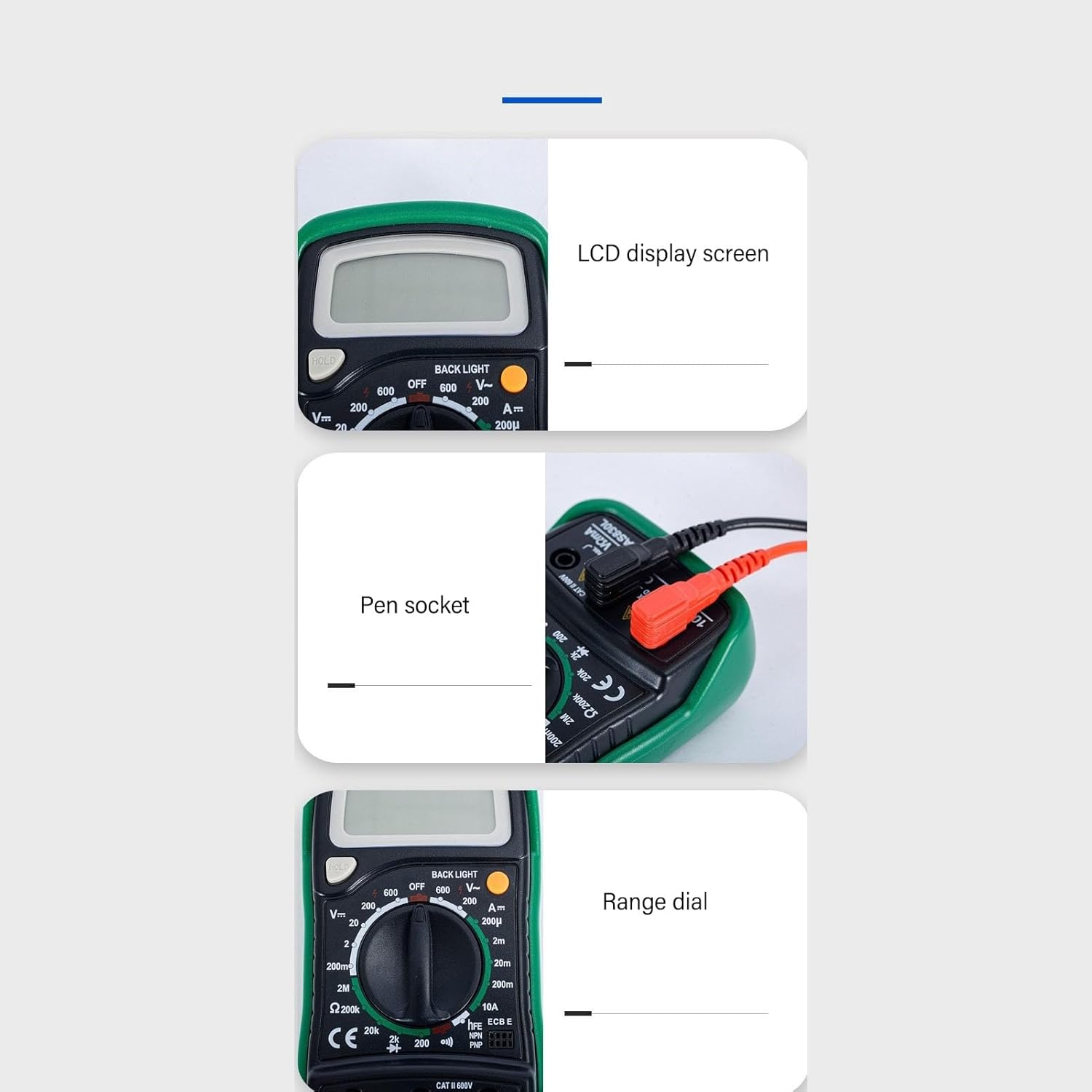
- LCD Display: Shows measurement readings, units, and indicators. Features a backlight for clear reading in various lighting conditions.
- Rotary Dial: Used to select the desired measurement function (e.g., AC/DC Voltage, Resistance, Current, Diode, Transistor, Continuity).
- Input Jacks:
- COM (Common): For the black test lead (negative).
- VΩmA: For the red test lead (positive) for voltage, resistance, and milliampere current measurements.
- 10A: For the red test lead (positive) for high current (up to 10A) measurements.
- HOLD Button: Freezes the current reading on the display.
- BACKLIGHT Button: Activates the display backlight.
- hFE Socket: For testing transistors (NPN/PNP).
4. Setup
4.1 Battery Installation
The multimeter requires one 9V (6F22) battery (200mAh capacity) for operation. To install or replace the battery:
- Ensure the multimeter is turned OFF and disconnect all test leads.
- Locate the battery compartment cover on the back of the unit.
- Remove the screw(s) securing the cover and carefully lift it off.
- Connect the 9V battery to the battery clip, observing correct polarity.
- Place the battery into the compartment and replace the cover, securing it with the screw(s).
NOTE: Replace the battery immediately when the low battery indicator (-+) appears on the display to ensure accurate measurements.
4.2 Connecting Test Leads


Always connect the black test lead to the "COM" jack. Connect the red test lead to the appropriate jack based on the measurement type:
- For Voltage, Resistance, Diode, Continuity, and small Current (mA): Connect the red lead to the VΩmA jack.
- For large Current (up to 10A): Connect the red lead to the 10A jack.
5. Operating Instructions
5.1 General Measurement Process
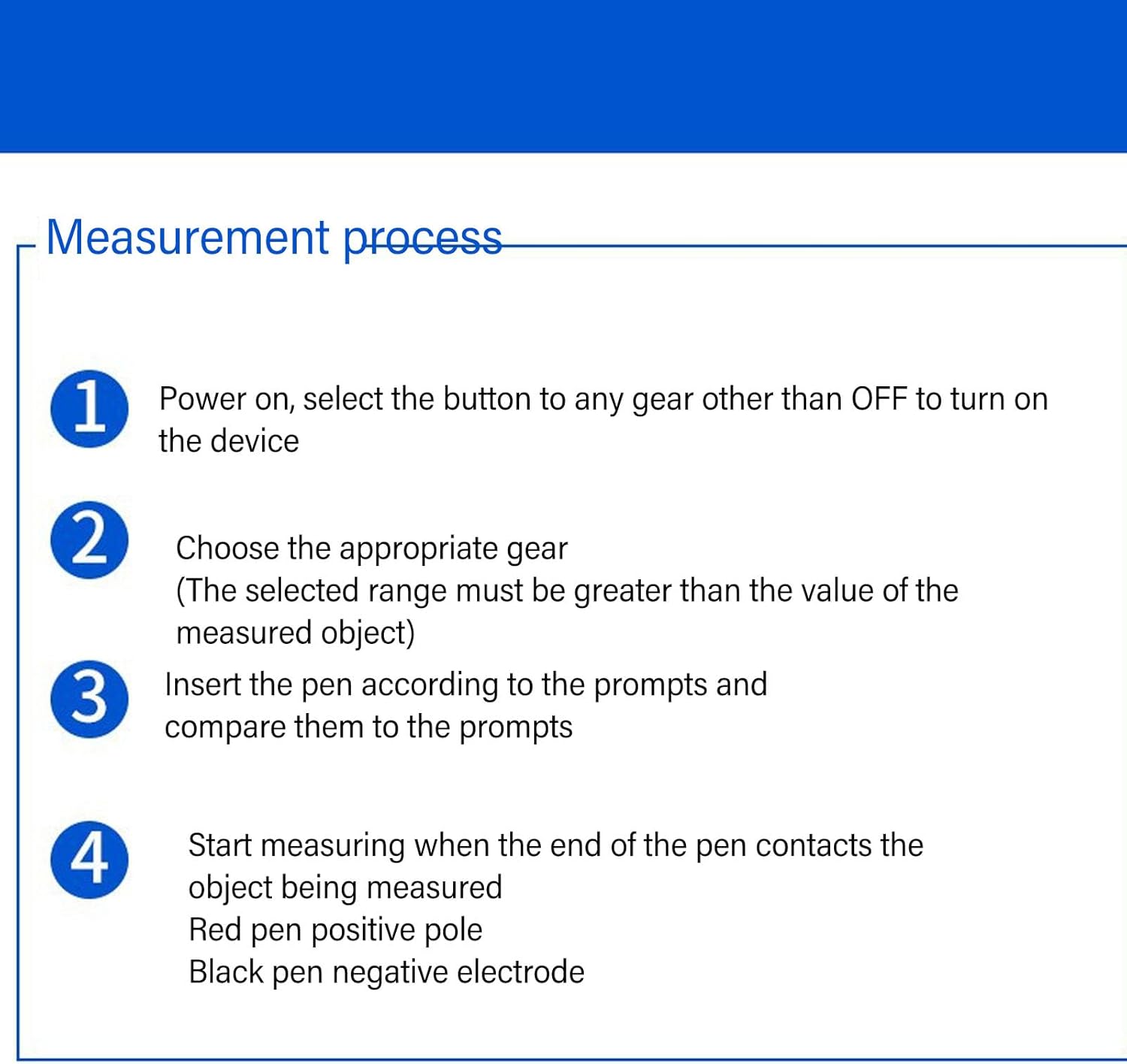
- Power On: Turn the rotary dial from the "OFF" position to any desired measurement function.
- Select Range: Choose the appropriate range for your measurement. The selected range must be greater than the expected value of the object being measured. If the value is unknown, start with the highest range and work downwards.
- Insert Test Leads: Connect the black test lead to the "COM" jack and the red test lead to the appropriate input jack (VΩmA or 10A) based on the measurement type.
- Measure: Carefully touch the test probes to the circuit or component being measured. The red probe is for the positive pole, and the black probe is for the negative electrode. Read the value on the LCD display.
5.2 Specific Measurement Functions

5.2.1 DC Voltage Measurement (V=)
- Set the rotary dial to the desired "V=" range (e.g., 200mV, 2V, 20V, 200V, 600V).
- Connect the black lead to "COM" and the red lead to "VΩmA".
- Connect the test probes across the DC voltage source or component in parallel.
- Read the voltage value on the display. If a negative sign appears, it indicates reversed polarity.
5.2.2 AC Voltage Measurement (V~)
- Set the rotary dial to the desired "V~" range (e.g., 200V, 600V).
- Connect the black lead to "COM" and the red lead to "VΩmA".
- Connect the test probes across the AC voltage source or component in parallel.
- Read the voltage value on the display.
5.2.3 DC Current Measurement (A=)
- Set the rotary dial to the desired "A=" range (e.g., 200µA, 2mA, 20mA, 200mA, 10A).
- For ranges up to 200mA, connect the black lead to "COM" and the red lead to "VΩmA".
- For the 10A range, connect the black lead to "COM" and the red lead to "10A".
- WARNING: Connect the meter in series with the circuit. Do not connect it in parallel across a voltage source. Ensure the circuit is de-energized before connecting the meter.
- Apply power to the circuit and read the current value.
5.2.4 Resistance Measurement (Ω)
- Set the rotary dial to the desired "Ω" range (e.g., 200Ω, 2kΩ, 20kΩ, 200kΩ, 2MΩ, 20MΩ).
- Connect the black lead to "COM" and the red lead to "VΩmA".
- Ensure the circuit or component under test is de-energized. Disconnect the component from the circuit if necessary to avoid parallel resistance paths.
- Connect the test probes across the component.
- Read the resistance value on the display.
5.2.5 Diode Test (→|)
- Set the rotary dial to the "Diode" position.
- Connect the black lead to "COM" and the red lead to "VΩmA".
- Connect the red probe to the anode and the black probe to the cathode of the diode. The display will show the forward voltage drop (typically 0.5V to 0.8V for silicon diodes).
- Reverse the probes. The display should show "OL" (Open Loop) for a good diode. If it shows a reading in both directions or "OL" in both directions, the diode is likely faulty.
5.2.6 Continuity Test ())))
- Set the rotary dial to the "Continuity" position.
- Connect the black lead to "COM" and the red lead to "VΩmA".
- Ensure the circuit or component under test is de-energized.
- Connect the test probes across the circuit path or component.
- If the resistance is below approximately 50Ω (this value can vary slightly by meter), the buzzer will sound, indicating continuity. The display will also show the resistance value.
5.2.7 Transistor (hFE) Test
- Set the rotary dial to the "hFE" position.
- Identify if the transistor is NPN or PNP.
- Insert the transistor's emitter, base, and collector leads into the corresponding holes in the hFE socket on the meter.
- Read the hFE (DC current gain) value on the display.
6. Specifications
This section details the technical specifications of the Walfront Digital Multimeter WALFRONTvyu716zt9a.
| Feature | Specification |
|---|---|
| Model | WALFRONTvyu716zt9a (MAS830L) |
| Material | ABS, Rubber |
| Battery Type | 9V (6F22) battery x 1 |
| Battery Capacity | 200mAh |
| Maximum Display Value | 1999 (3 1/2 digits) |
| Overload Indication | "1" on display |
| Polarity Display | Negative polarity display "-" |
| Operating Temperature | 0 to 40°C |
| Low Battery Indication | Display shows "-+" |
| Maximum Voltage Input (V-Ground) | CAT II 600V |
| Fuse Protection (mA input) | F 200mA 250V |
| DC Voltage Range | 200mV, 2V, 20V, 200V, 600V |
| AC Voltage Range | 200V, 600V |
| DC Current Range | 200µA, 2mA, 20mA, 200mA, 10A |
| Resistance Range | 200Ω, 2kΩ, 20kΩ, 200kΩ, 2MΩ, 20MΩ |
| Diode Test | Yes |
| Continuity Test | Yes (with buzzer) |
| Transistor hFE Test | Yes |
| Features | LCD Backlight, Flashlight, Ergonomic Grip, Overload Protection |


7. Maintenance
7.1 Cleaning
To clean the meter, wipe the case with a damp cloth and a mild detergent. Do not use abrasives or solvents. Ensure the meter is completely dry before use.
7.2 Battery Replacement
Refer to Section 4.1 for instructions on battery replacement. Always use a fresh 9V (6F22) battery.
7.3 Fuse Replacement
If the current measurement function (especially mA range) stops working, the fuse may need replacement. The fuse for the mA input is rated F 200mA 250V. To replace the fuse:
- Ensure the multimeter is turned OFF and disconnect all test leads.
- Open the battery compartment cover (refer to Section 4.1).
- Carefully remove the old fuse and replace it with a new fuse of the identical type and rating.
- Securely close the battery compartment cover.
WARNING: Never use a fuse with a different rating. This can lead to meter damage or personal injury.
7.4 Storage
When not in use for extended periods, remove the battery to prevent leakage and store the multimeter in a cool, dry place away from direct sunlight and extreme temperatures.
8. Troubleshooting
This section addresses common issues you might encounter with your multimeter.
- Meter does not power on:
- Check if the battery is installed correctly and has sufficient charge. Replace if necessary.
- Ensure the rotary dial is not in the "OFF" position.
- No reading or "OL" (Overload) displayed:
- Ensure test leads are properly connected to the correct input jacks and the circuit.
- Verify that the selected range is appropriate for the measurement. If "OL" appears, the value exceeds the current range; select a higher range.
- For resistance measurements, ensure the component is disconnected from the circuit.
- For current measurements, ensure the meter is connected in series.
- Inaccurate readings:
- Check battery level; a low battery can affect accuracy.
- Ensure test leads are making good contact.
- Verify the correct function and range are selected.
- Avoid strong electromagnetic fields during measurement.
- Current measurement not working:
- Check if the fuse for the current input is blown. Refer to Section 7.3 for fuse replacement.
- Ensure the red lead is connected to the correct current input jack (VΩmA for mA, 10A for 10A).
9. Warranty and Support
Specific warranty information and direct customer support contact details are not provided in the product description. For warranty claims or technical assistance, please refer to the retailer or manufacturer's official website where you purchased this product.
The product is designed for durability with features like shockproof rubber material and intelligent overload protection, as shown in Figures 6.1 and 6.2, indicating a focus on product longevity and safety.